xiphmont: (Default)

Hello all! I'm traveling to Norway this week to give a few talks and a workshop on online video, all sponsored by the Norwegian Unix Users Group. The workshop is likely to cover technical details of the new AV1 codec (and free codecs in general), while the talks are intended more as a free codec tea party.

Talks and meetups: "Fighting for free video - technical tactics and war stories from the FOSS audio and video codec frontier"

The talks are free and open to the public.

Workshop: "Audio and video format workshop with Xiphmont"

  • Wednesday April 24 at 10:00am at Cisco

The workshop is open to interested professionals, and I expect it to be more technical. Please contact NUUG (information in the links above) if you wish to attend.

Do come!

xiphmont: (Default)

Jean-Marc Valin has been applying deep learning frameworks to audio over the past few years. So far he's released RNNoise (a surprisingly good/fast denoising system) and LPCNet (a speech synthesis system along the lines of WaveNet, but fast enough to use realtime on commodity hardware).

Now he's built a codec out of LPCNet.

"A Real-Time Wideband Neural Vocoder at 1.6 kb/s Using LPCNet" presents a new wideband speech codec built out of the best parts of a brutally speed and space efficient vocoder paired with deep-learning analysis and excitation. It's alpha-grade research in a lot of ways, but decidedly not vapourware. You can download the source and play with it now, but first, go have a look at the demo page.

xiphmont: (Default)

The holidays are over and I'm back to having a little hobby time here and there. With the LED mod assembled and in place, the coaxial illuminator is certainly much brighter than the original halogen-powered unit. Of course, an LED ring light still utterly destroys it, but the brightness level of the modded version is usable in a lit room, where the original halogen version really wasn't. So, yay.

However... contrast is damaged somewhat? Did I get some optics dirty?

A little investigation reveals our problem is at the primary constraint in the optical path. Specifically, the coaxial illuminator is designed to focus down an image of the light source right at the plane of the internal adjustable iris in order to get as much useful light through it as possible. You can see the glowing filament clearly when the iris is nearly closed, and it passes through cleanly with the iris open.

When the light doesn't clear the iris but shines on it instead, the light pollutes the image. Interestingly, this means the adjustable iris and coaxial illuminator don't really coexist well, a problem I hadn't noticed before but yup.... sure enough... the illuminator is only really useful with the iris wide open.

Possibly for this reason, the slightly later SZH10 dispenses with the adjustable iris for a fixed aperture, instead offering the iris as an accessory 'slice' that can be placed later in the optical path. This neatly avoids the contrast problem.

In any case, my problem is 90% a slight misalignment, easily dealt with.

That said, the square die image is just a bit too large to fit cleanly through the round iris opening even when aligned. A little optimization of my illuminator optics is probably called for.

But... can I actually do better? Olympus knew what they were doing, and if there was an obviously better lens design they'd have used it, right?

Stay tuned for our next exciting episode!

xiphmont: (Default)

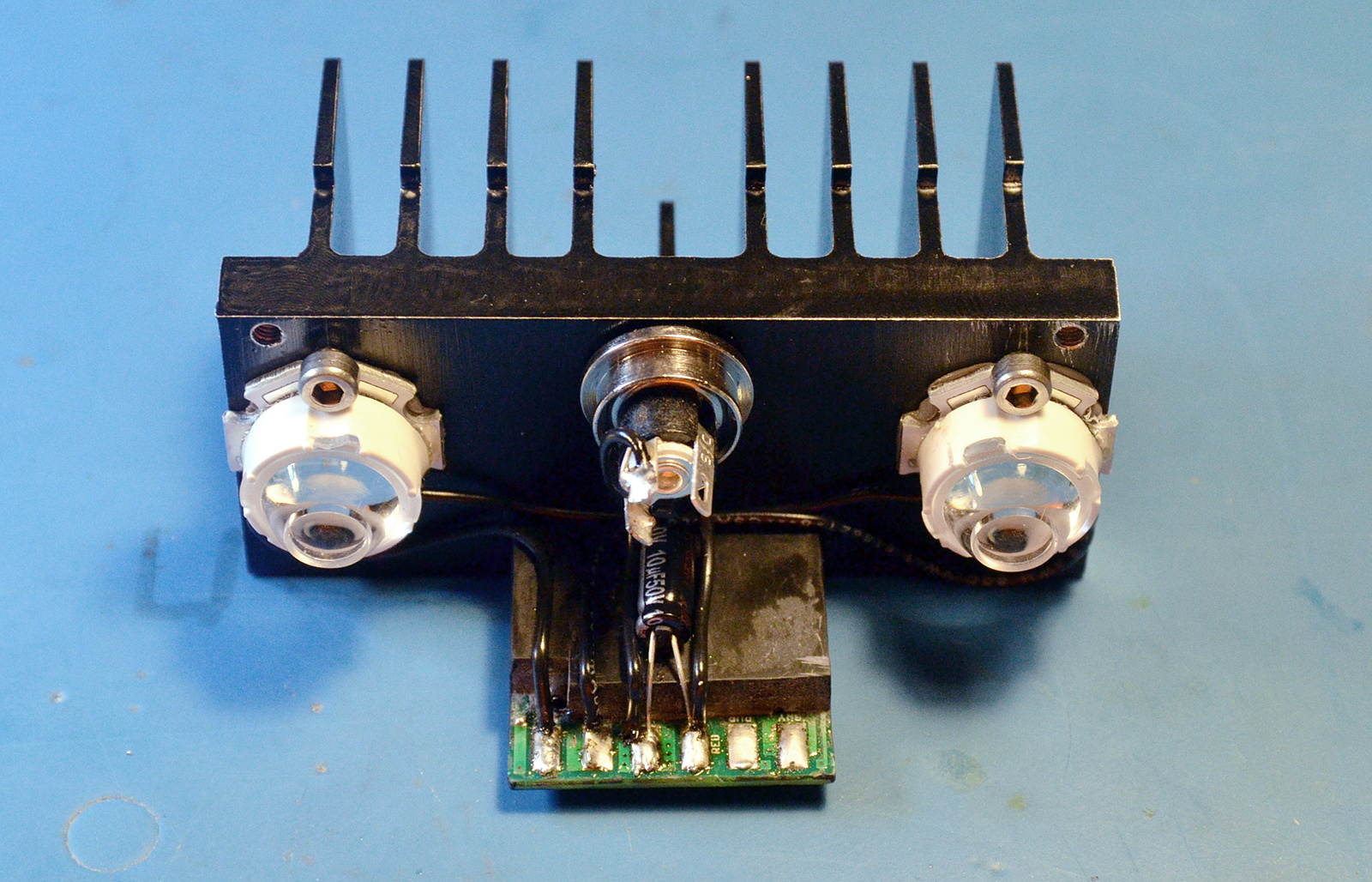
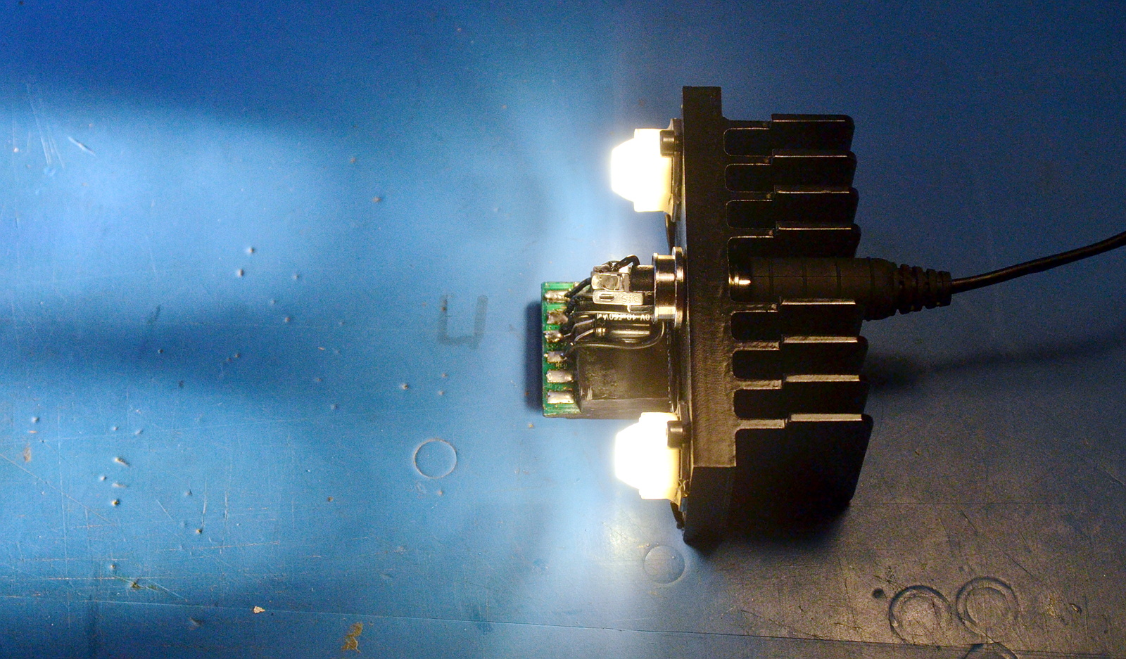
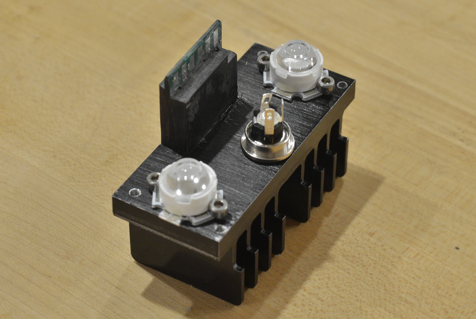
The end result of more playing around with the plastic LED collimaters: they're not going to work well. Dang.

The microscope wants a small diameter parallel light beam, and the plastic collimaters just won't do that. Even the tight spots overfocus and overmagnify, and there's no real room for adjustment.

Noq2's approach works because of:

a) brute force: 60W of LED light is the equivalent of around 350W of halogen light

b) a large die LED (7mm diameter!): that's more like a small COB

In his case it's a 'close enough' approximation to infinity focus because of the huge die and tons of output. There's enough nearly parallel light in there along with all the rest to make it work. Most of the light that makes it into the optical path (which is likely only 5-10%, the beamsplitter doesn't combine much) is just lighting up the inside of the microscope body, but the light that does make it all the way through is diffuse and even and nice. Brute force works!

Me, I want as much of the light to be usable as I can get.

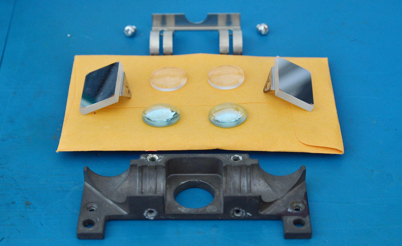
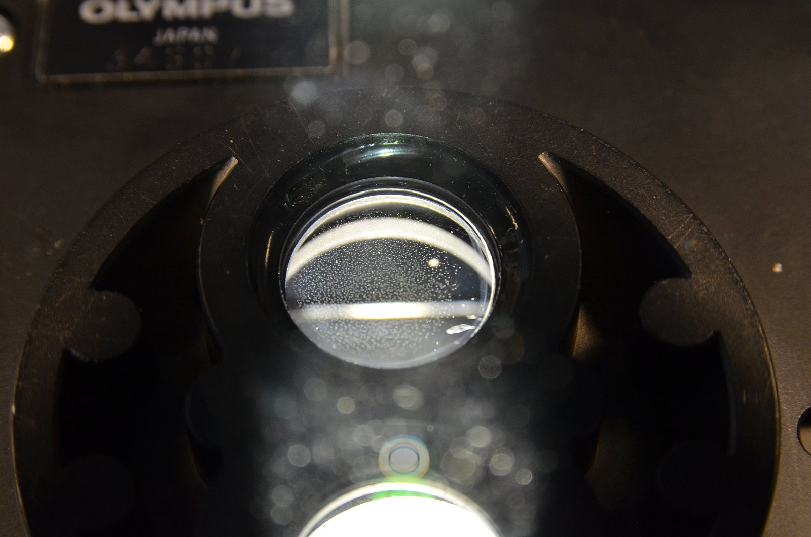
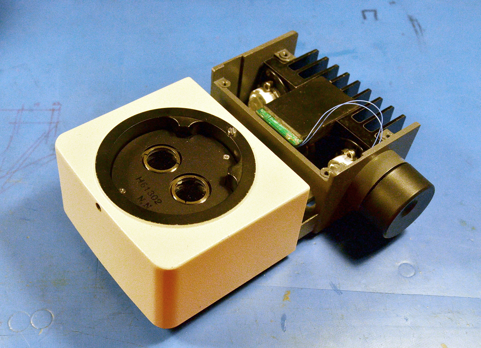
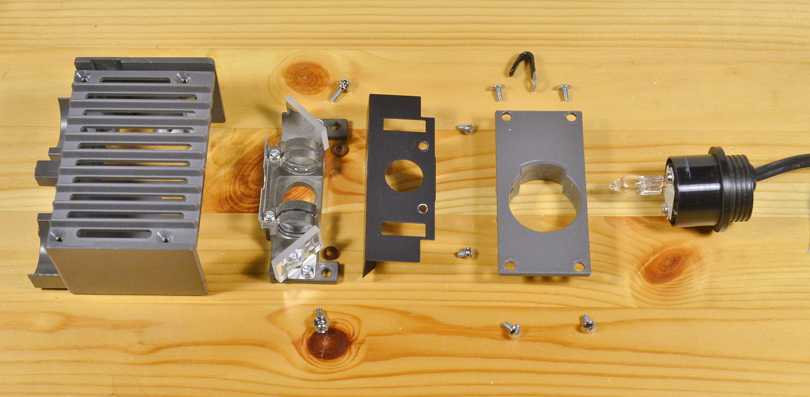
So I'm probably back to using lenses. The stock Olympus setup uses two air-gapped elements with a total focal distance of 11-12mm placed on either side of a halogen bulb. The bulb filament intentionally sits just in front of the focal point to defocus the image slightly. (EDIT: Actually, I'm wrong here; it's just past the focal point in order to produce a focused image of the bulb filament at the point of the iris in the microscope body).

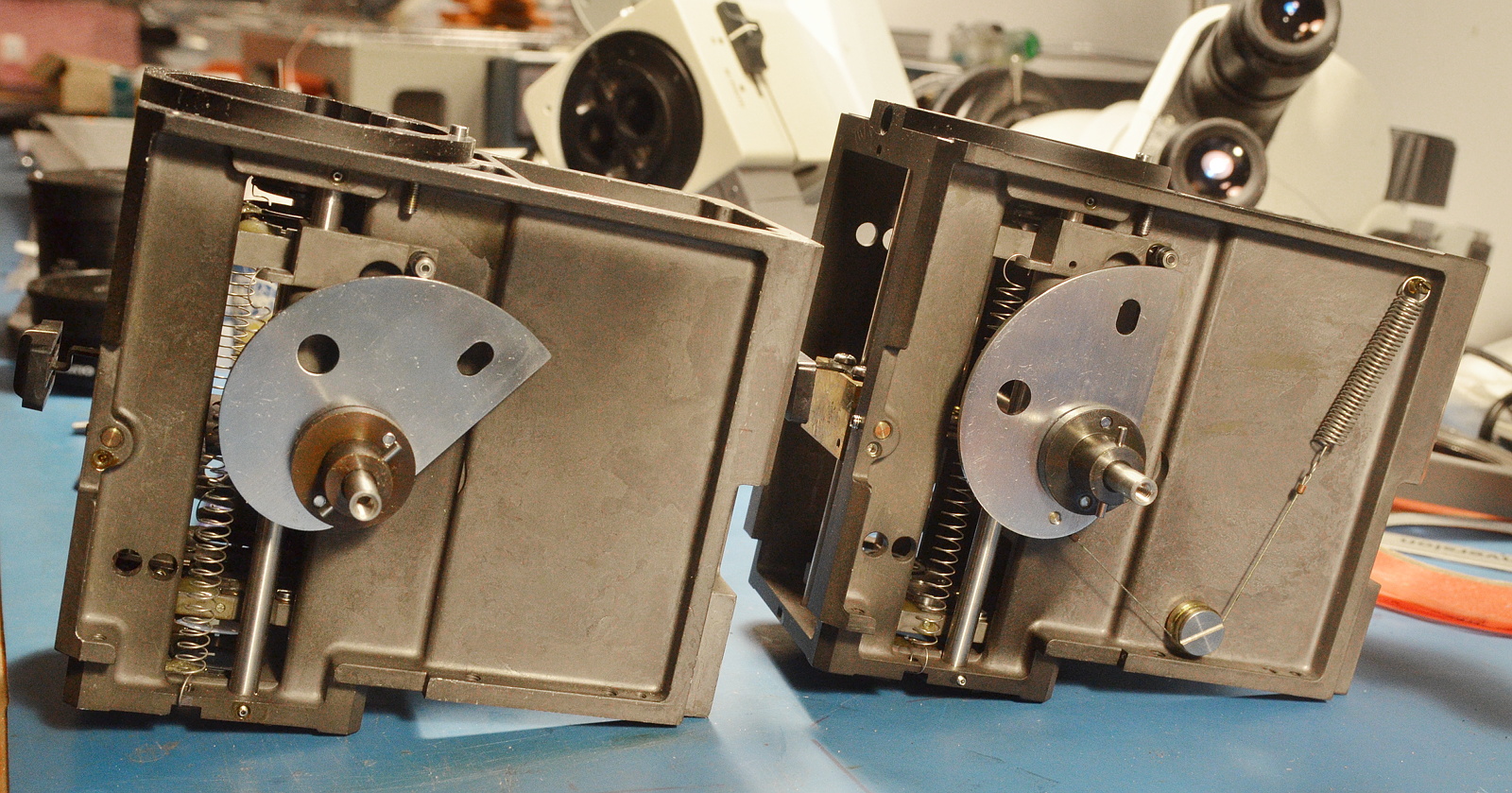
Olympus uses some really nice glass. The first condenser element is a partial shortpass to filter out some of the infrared. The second weaker element nearly touches the first and finishes the collimation job. Two 45 degree front-surface (!) mirrors direct the light into the beam combiner body.

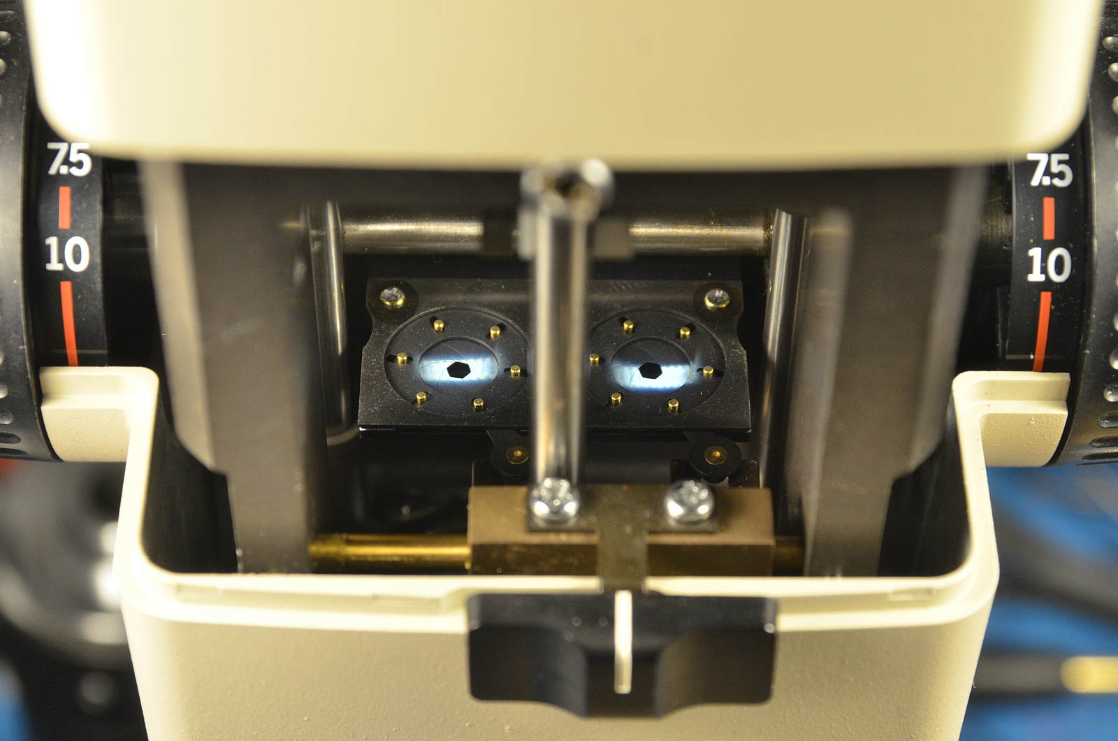
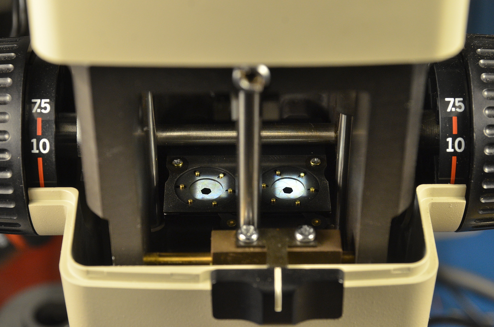
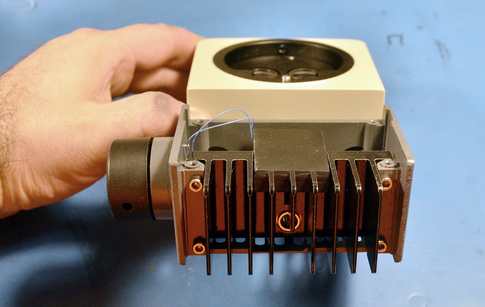
The biggest constraint on the collimater design is the diameter of the optical path through the scope, which is a little under 15mm at multiple points. Opposing that, we want to collect as much light as possible from the LED into the condenser, which means putting the lenses as close to the emitter as possible, and so choosing the shortest practical focal length. Focal length trades off against beam width; the shorter the focal length, the more the 'image' of the LED die is magnified and the wider the final collimated light beam.

The original Olympus optical design expands the image of the halogen bulb filament into a beam of approximately 15mm diameter, matching the optical path. The Cree XP-L LEDs I'm using have a die almost the same major dimension as the bulb filament.
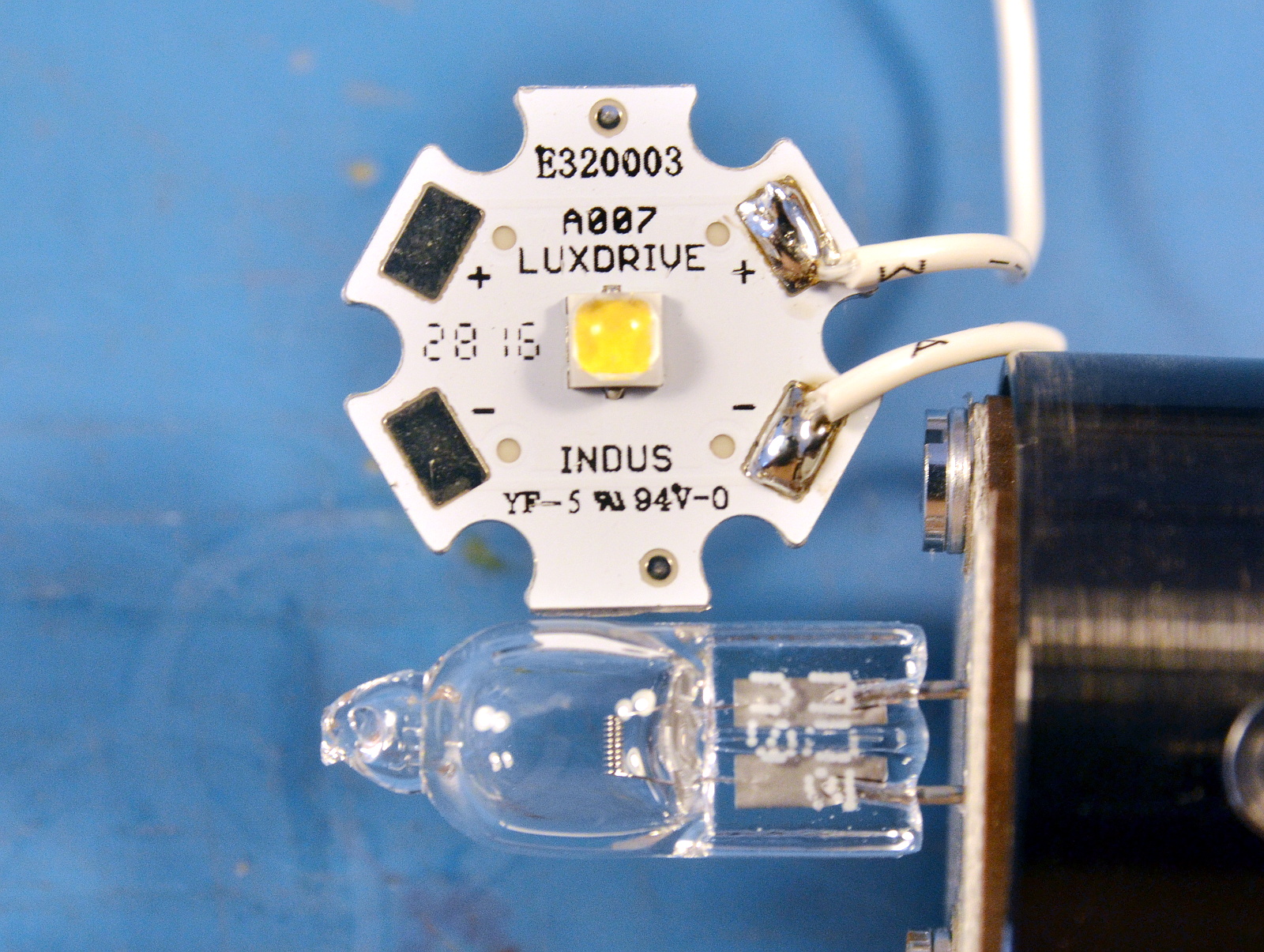
A more powerful LED with a bigger die probably isn't useful if we're going to use a single-stage collimator. And an XP-L is easily the highest-flux LED I can get with a die this small.

The XHP70.2 might put out 5x as much light, but if that's over 5x as much area, it's not a net gain given the constraints (I'm going to test it anyway, but I don't have high hopes). The big die of the XHP70.2 isn't a problem for noq2 because he's not using any optics that magnify its apparent size. He could usefully apply a 15mm COB.

This also means we're not going to improve on the original Olympus lens choices without going to a more complex beam reduction design that probably won't fit. (EDIT: Actually, I can probably fit a Keplerian design in there)

I'm going to try it Olympus's way. Given how dang nice those lenses are, I'm totally yoinking them. And since I'm messing so much with the physical layout, I want some adjustment ability. Which means at this point-- I'm most of the way back to my original design. Oh well. At least much of it is actually built and this has become an iterative process. A little at a time rather than one fell swooooooop.

So... The next step is making some new lens tubes.

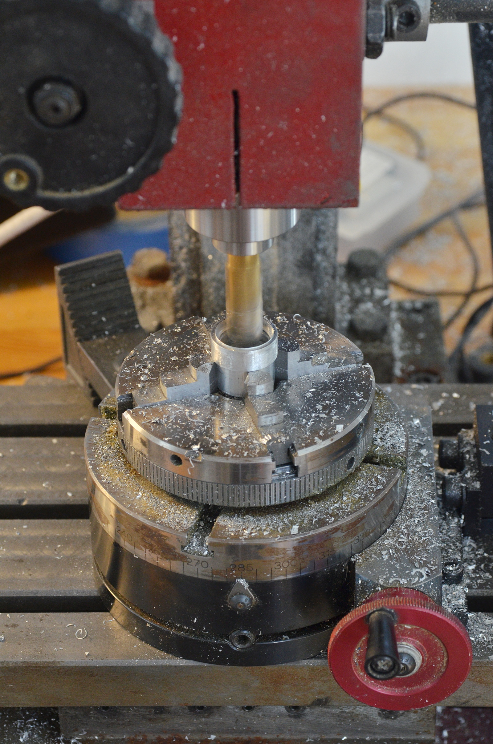
And mounting the Olympus lenses in them (using nice, reversible, not messy O-rings).

This gives me the lenses at the proper separation in a durable, flexible package. Now I have to make a tube mount that fits inside the lighting enclosure.

xiphmont: (Default)
Oh. I think I discovered the real reason this coaxial illuminator was only $90, which was cheap even with missing accessories:

The main stereo-path doublets are disintegrating. That 'sand' in the lens is the optical cement bonding the lenses together breaking down.

The good news is I have spares, and the spares appear to be fine. I suppose I could also disassemble and re-cement them, though I don't trust myself to do an Olympus-level alignment job.

xiphmont: (Default)

Electronics assembly!

But does it, for the lack of a better word, chooch?

Yes, it chooches.

Adding the pot to test the adjustment, it turns out my BuckBlock is sourcing more than 500uA-- it's actually closer to 625uA. Also, it's firing up at ~1.5v rather than ~ 1.75v. That means I want a 2.2k low-end resistor and a lower pot resistance. So I modded another 10k linear pot into a 13k exp-ish pot, and continued assembly.

Everything goes together as intended and looks nice.

But there's a snag; I knew there was a good chance the optics wouldn't play as well with the SZH as I hoped, and in fact, the focus behavior isn't working well once on the scope. The illuminator works, and alignment is spot-on, but it's focusing an image of the lens at working depth, which is suboptimal. Also due to the suboptimal focus, lots of light is getting wasted inside the scope as it scatters out of the parallel-light/infinity focus portion of the optical path.

I'm going to have to play more with it.

xiphmont: (Default)

After evaluating several different canned collimators, I chose the oddball Ledil Tina spots as having the best behavior when used with the illuminator head optics. They're stick-ons, so I stuck 'em on, and added a few tacks of UV-cure resin as well.

Inital heatsink assembly with LEDs, DC jack and BuckBlock looks good!

The intensity adjustment on the BuckBlock is voltage controlled and sources 500uA; the data sheet suggests feeding it through a 20k potentiometer to ground. That has two [minor] problems.

I'm using a pot with detents, and the way the adjustment curve goes, I'd end up with dead notches at both ends of the adjustment range. Second, the adjustment curve is linear and it would be nice to have more resolution in the low range. Intensity perception is exponential.

The first problem could be solved by using a 15k pot and adding a fixed 3k resistor at the lower end. The second problem is usually solved by using a log-taper pot (or in this case, I'd need an exponential, so I'd hook it up 'backward'). The problem is no one makes log-taper 15k pots, and certainly none with detents. Also, I already have linear-taper 11-detent 10k pots, and I don't feel like wasting them.

The usual trick of turning a linear-taper pot into a log taper with an extra resistor doesn't work here. I need an exponential taper, not a log taper. This is where older tinkerers usually start whipping out transistor circuits, and the more recent crowd embeds an entire microcontroller and writes software to get the desired curve.

I'll admit I played with a transistor circuit for a little while but my pots turn out to have a third problem-- the first and last steps are 1/5th the step size of the middle eight. That's when I realized I didn't want to work around a suboptimal part. The right part makes all these complications go away, and I can have the right part.

These pots are just carbon-element-on-phenolic-inna-can. So I pried the can open, and scraped the resistance element into the resistance and curve I wanted with a hobby knife. I cut the last step into an open (which will cause the adjustment's current source to float up to full-range), and trimmed the first step down to give a bigger step.

Now I have a the right part: a 15k pot that goes exactly to full-range in increasing steps. No additional electronics.

Today's work is done: I need to let the silicone holding the BuckBlock in place cure and the paint on the adjustment boss dry. Tomorrow I wire it up and test the assembled electronics.

xiphmont: (Default)

Earlier this year, when I was building mods for my Olympus SZH microscope, I planned a coaxial illuminator using LEDs. The design got... a little out of hand...

...and I put it aside.

Last week I stumbled upon noq2's blog, where he documented his LED mod for the same microscope. It's the polar opposite to what I was doing. His is simple, brute force, and gets the job done. Go have a read, it's nicely done (and his animated gifs of the SZH internals are great). And did I mention it's actually finished and working? :-)

This inspired me to reconsider what I was doing.

I mean, I know what I was thinking: a design worthy of the rest of the absurdly overbuilt Olympus. I mean, just look at the original collimator! They use front-surface mirrors in the light source!

Also I didn't want to sacrifice any original Olympus parts. Complete SZH coaxial illuminators still sell for over a grand. But that's mostly because they're usually missing accessories needed to operate them (the bulb holder and transformer) which I didn't need. Last summer I picked up a bare illuminator block for $90. That's cheap enough I'm willing to mod it permenently.

Then I saw noq2's build. It was brilliant. And even better, I can have everything I originally wanted with a dead-simple addition.

The whole 'tactical flashlight' craze has spawned a smorgasboard of cheap, canned collimation optics for LEDs. They're even better than lenses as they sit all around the emitter instead of a distance in front, so they catch more light. Most are 90%+ efficient.

So I'm taking what noq2 did and slapping a $2 spot-collimator on front. No muss, no fuss. Well, I have to fuss a bit, so I'll put the driver electronics inside the housing, and add an intensity adjustment too. Still not *much* fuss.

...beginning with hacking off a big ol' chunk of heatsink using a dull beaver...

and cleaning it up a bit on a sharper beaver.

Trim to fit the existing enclosure, with an eye toward reusing the existing mounting holes on the enclosure's rear boss. Also drill and tap holes for LED mounting, power jack, and a notch for a BuckBlock controller, and we end up with something like:

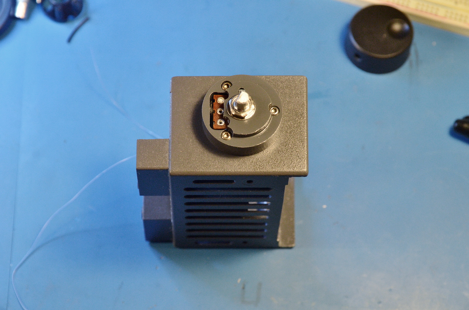
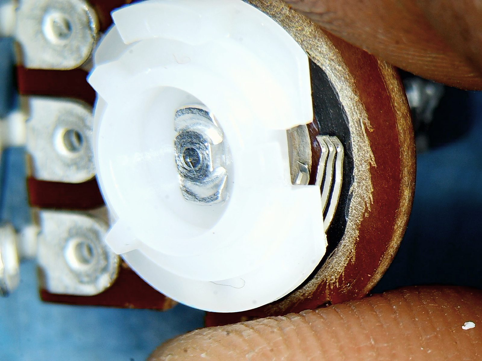
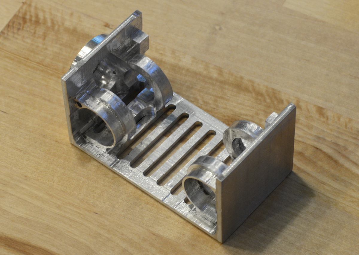
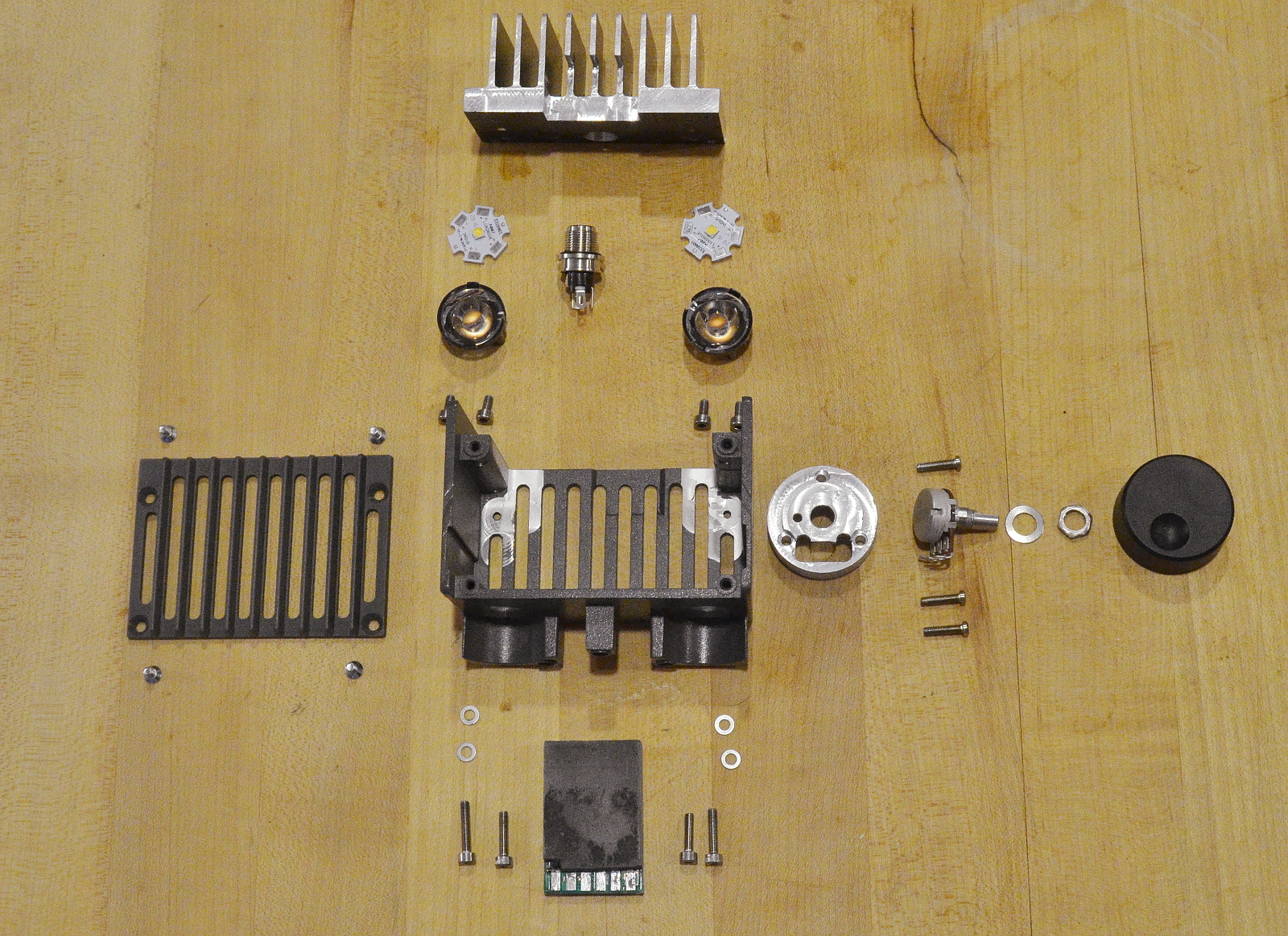
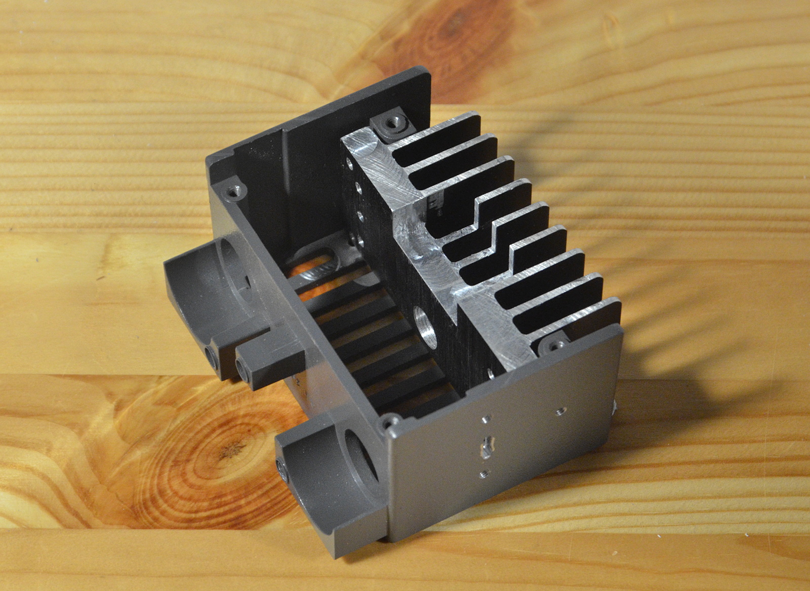
I want an intensity adjustment knob, so I stole the boss off the prototype I machined earlier this year. Along with bolts, a really nice 11-position-with-detents potentiometer, and the aforementioned LED optics (but not including wires) we finally end up with this exploded build:

Next up will be a little paint, a schematic, and build/test.

xiphmont: (Default)

I have two assembly microscopes: A mediocre Chinese AmScope (which is nonetheless convenient, small, and a pleasure to use) and a monster 1980's Olympus SZH for when I need resolving power, like high-resolution photos.

Aside from size, the SZH has a big annoyance: The zoom setting won't stay put at low magnification. It's a cam and roller mechanism with real bushings and bearings throughout, and it's so low-friction that the stage springs constantly pull the zoom out of the low magnification range. I'm guessing this is part of the reason for the click-detent system in its successor.

I picked up another SZH body recently for parts, just in case, and it didn't have the same problem. It needed a serious cleaning, so I opened it up. And HUH.

What do you know. Olympus added a counter-balance spring at some point. Completely eliminates the problem.

xiphmont: (Default)

Performance-wise, 1.3 is the biggest Opus update so far. Several commenters have suggested it should have been named 2.0, but full interoperability is important, and '2.0' could suggest we broke compatibility somehow (we haven't).

Opus 1.3 adds full Ambisonics surround support, improves the built in speech/music detection, and greatly improves low bitrate performance. Wideband speech now goes down to 9kbps, narrowband to 5kpbs, and stereo performance improves especially in the 24-32kbps range.

Go forth and deploy!

xiphmont: (Default)

The latest of the 51nb upgrade mobos for classic thinkpads is the X210, a drop-in replacement motherboard for the X201. It's a Kaby Lake with lots of goodies, and it makes the screens that were available for a stock X201 seem even more limiting (that is, unforgivably crappy) than they were when the X201 was new.

People have always stuffed better screens into an X201, and that's been taken to new levels with the advent of the X210. It sports the original LVDS connector, but also has a weird two-lane eDP connector (apparently matching a popular Chinese screen) along with two more unexposed eDP lanes unexposed but accessible.

The thing I always hated about the X201 was the miles of bezel in a lid more than thick enough to swallow a much bigger screen. Well, that and the 16:10 ratio. The X61 will always be my fave for being 4:3.

That said, the dimensions suggest it should be possible to fit a pretty good sized modern 3:2 screen. One 51nb modder went to heroic lengths to fit a 12.9" Chromebook screen, but it required losing the latches, the status LEDs and a decent amount of internal bracing. And custom driver and backlight hardware. I had one of these screens and verified the fit was.. difficult at best. I wouldn't trust what was left of the lid after stuffing the screen inside to handle any kind of abuse.

But since then, LG released a 13.0" 3000x2000 that's physically smaller with a larger active area and no special electronics needs, part number LP130QP1.

I ordered one. It arrived today.

It will fit without heroics, though I'll certainly want to brace the screen (so incredibly thin!) But does it light?

Why, yes. Yes, it does.

Time to make another custom PCB and matching flex cables!

xiphmont: (Default)

tl;dr summary: many (most?) of the 12" HV121P01 SXGA screens with a 'bathtub ring' or 'retro-tv' effect around the edges are not defective, VR1 simply got knocked out of adjustment.

THE WHOLE STORY:

This is one of those occasions where I feel like a complete idiot and simultaneously wonder how nobody else noticed this before.

I experimented a while back with chemically stripping the front glass off HV121P01-101 screens, since these were plentiful (at the time) but you had to remove the glass and bonding adhesive to use them in an X61/X62. Mechanical stripping is labor intensive to put it mildly, and using xylene or alcohol seemed like a useful shortcut. It worked, but it also damaged the polarizer films in exactly the way illustrated in the picture.

At the same time, people were getting reclaimed screens from China showing the exact same effect. I got one or two of these myself, and the polarizer films were in fact damaged just like I saw on the screens I stripped.

And I assumed from there on out that chemical/heat stripping was the only explanation of the effect. Which turns out to be terribly wrong.

Most LCD screens have a variable resistor adjustment as part of a temperature/drive compensation circuit. I played with it on many screens in the past, and it was a way to alter either the absolute drive or overdrive speed of the entire screen, usually affecting gamma and contrast in some fashion.

That's not what it does on an HV121P01.

I was modding some of the screens I'd recently bought for LED backlight, screens which I'd tested carefully on receipt and found no defects. After modding, three turned up 'bathtub ring' defects when tested. The defect appeared spontaneously, and others had noted this happen after doing an LED mod. At the time, this was deeply disappointing, perplexing and expensive. I was not going to sell any defective screens no matter how subtle the defect.

Did the LED mod cause the fault? It had been near 100% humidity in NH all that week, did that do it? Was it a fault that was always there and only showed up with LEDs? Or was it always there and I had simply missed it?

I peeled and inspected the polarizers on one screen; this panel had a replacement polarizer that was glossy, so it wasn't going to be saleable anyway. And if chemical stripping had caused the defect, missed till now, why did the *replacement* films show the problem? They didn't, in fact--- after removal and testing, they were faultless, perfectly regular in every way.

I queued up a second panel for testing (I didn't want to burn my own replacement films on a potentially bad panel). Everything about it looked perfect until I was displaying low-brightness gray-to-gray stipple patterns, and that's when the bathtub pattern appeared. Could it be some sort of mismatched signal drive? I looked at VR1, which I'd never touched because I was sure I knew what it did.

So I tweaked it. And the problem got worse. I tweaked it the other direction and the problem disappeared.

I'm still testing in detail to make sure this isn't multiple unnoticeable problems stacking up into a noticeable one, but it sure looks to me right now that this is an adjustment to balance panel drive in the center versus the edges of the screen. It's normally fixed after adjustment at the factory with a little lacquer, but it's not the slightest bit surprising it might get knocked loose or dissolved during rebuilding or modding.

VR1 probably can't mitigate a genuinely frotzed polarizer but it's obviously worth trying it just to see if it was never the polarizer at all.

xiphmont: (Default)

Following up on my previous post about finding a source of legit NOS 12.1" SXGA screens for X62 builds, the most recent batch I ordered was not all roses. So proceed with caution.

First and foremost, these screens definitely are not and never were true NOS. Since getting a few duds (more in a bit) I've dug through all their ROM contents, and the model and serial numbers don't match up between components. In fact, I think whoever's rebuilding them has access to equipment for heat-bonding flex cables, because I don't think all the controller boards even match the glass matrices.

That's not really a problem in and of itself. These parts were mostly interchangeable, and I approve of not wasting good bits if you can mix and match them into perfectly good screens.

Unfortunately, I've gotten a few screens with glue seeping into the diffusers, and using replacement polarizer films that don't match OEM. The semi-unforgiveable sin was a few panels showing up with *glossy* front films.

Overall, I've still had better luck overall with these screens than most of the rebuilds I've bought in the past. Four years ago, crappy rebuilds were going for $300+. Even if I'm getting a few duds I'm not going to pass along, the hit rate is still better than it has been in a while.

xiphmont: (Default)

There's some good LCD news though-- I found a seller who's trickling out small numbers of refurbished HV121P01-100 screens, and unlike all the others I've sampled in the past several years, these have so far been excellent. Yes, they're rebuilt, but they appear to use entirely genuine, model-appropriate parts. I have no idea if these are parts from B-grade panels being reassembled into new screens or what, but the results are NOS visual quality.

There's a 'downside': he actually seals the panels together with black RTV silicone. If you want to open the panel up to do further surgery, you can't. Or rather, with a thin spudger, a ton of patience and very very steady hands you can, but slip once and you'll crack the matrix. I did open some up to have a detailed look--- Yup! All genuine inside!

If you *don't* have any reason to open the screen up, the black silicone is a good idea-- it keeps grit out, and prevents the dreaded 'white spots' from ever developing. I've considered building screens this way myself, so I actually approve.

I'm importing a few of these for conversion to LED. If you want one, contact me about it. If you want to order directly yourself, it's item #710816705 on AliExpress. I have no idea how many per month he can actually make, or if the quality is going to hold up, but so far, so good!

xiphmont: (Default)

I've previously regaled you with stories of poorly rebuilt SXGA+ screens being sold as new that are the bane of X62 builders. Whelp, I'm beginning to think just about every in-demand LCD panel on AliExpress stands a good chance of being a barely serviceable, cobbled together pile of poo. Usually sold as "NEW" or "GENUINE" or "100% ORIGINAL" of course.

I'm building some T70s now, and the screens folks like to have in these are the IAQX10 2k 4:3 AFFS screens from the old IDTech joint venture. Like the SXGA screens for the X62, these are long out of production, still in demand, and hard to find in the wild. I've been working out how to mod the much thicker industrial -M version, which uses the same matrix, to work in a T70.

While I'm working that out, an IAQX10N seller pops up on AliExpress. The screens are expensive, but a genuine laptop version of this screen should be expensive at this point. I decided to buy just one so I had a comparison for my rebuild efforts.

Screen arrived, and lo and behold, it's a cobbled together pile of poo.

Immediately upon opening the box: the screen has a gloss front polarizer film. Uh oh. Stock is matte. Looking closer, it isn't even cut straight. Like, guys, at least use a straightedge.

Well, let's see if it at least works... and find it has a blank EDID. Uh huh. OK, let's get an IAQX10N EDID into it...

and we get:

The background on that screen? It's not supposed to be blue. It's supposed to be black. No, I didn't mess with the photo. 'Black' really looks like that. It's measuring less than 100:1 contrast; that blue is backlight bleed-through.

And the diagonal stripes? Not a trick of the picture. They're really there. It's Moiré patterning from using the wrong prism films for the given DPI, or not tacking them in-place and having them shift in transport.

This may well be the worst refurb job I've seen to date without being bent or cracked. Actually, I take it back, the outer frame is also slightly bent.

But hey! I'm only out $100 in shipping once I return it!

(In case you were wondering, the protective plastic film is still on the front of the screen in that picture, so all the bubbles and scratches are not real defects. But it does mean they did a lousy job putting the film on.)

xiphmont: (Default)

My second technology deep-dive article on the new AV1 codec is up, this time at Mozilla Hacks. It's a continuation of the video codec technology pages that I started with Daala.

"The Constrained Directional Enhancement Filter is the one we're interested in here; like the loop restoration filter, it removes ringing and basis noise around sharp edges, but unlike the loop restoration filter, it's directional. It can follow edges, as opposed to blindly filtering in all directions like most filters. This makes CDEF especially interesting; it's the first practical and useful directional filter applied in video coding."

xiphmont: (Default)

The T70 is about six months old, and I finally got around to buying one of the boards. I suppose it's time to build out the rest of a full fledged T701 :-)

Just like the BOE/Hydis SXGA+ HV121P01 AFFS screens are the desirable screens for an X62, every T70 builder wants the legendary IDTech QXGA IAQX10. The only ThinkPad this screen was ever offered in was, of all crazy things, the R61. It never appeared in a T-series, and wasn't used in many other laptops either. For a while there were surplus IAQX10N and IAQX10S models available on eBay, but those seem to have dried up.

That said, eBay and AliExpress are still full of the IAQX10M industrial model. It appears to be the same glass matrix with a slightly different controller, films, and a relatively large frame. It's about 2cm wider and taller than the laptop version, and more than twice as thick. There's no chance of fitting it in a laptop lid without serious modding. Of course, I'm not afraid of serious modding.

There's another problem to fix first. A ThinkPad (T70 included) won't even try to boot an LCD that doesn't respond to EDID (or responds with an invalid EDID for that matter). The IAQX10M is missing the EDID electronics present on the other versions and simply ties the EDID lines high.

0402 SMD is annoying, but it's not too hard to add the missing EEPROM (a standard 24C04), 4k7 SCL/SDA pullup resistors, a .1uF decoupling cap, three jumpers to tie the address lines to ground, and then move the jumpers on pins 4,6 and 7 to connect EDID power and un-tie the EDID lines. Removing the big capacitors around the 0402 pads and putting them back after adding the smaller components makes things considerably easier.

At this point, the ThinkPad still won't boot the panel, but it's possible to boot an OS (say Linux) with the blank pannel connected. Once the machine is on the net, it's no big deal to ssh in and flash a working EDID according to the instructions at ThinkWiki. Flash, reboot, working screen!

Now for the mods needed to make them fit.

xiphmont: (Default)

My first technical writing regarding the new AV1 codec is up at Xiph.Org. We've been working on AV1, heads-down, for a long time and my writing took a hiatus for almost that entire period. Now that it's out, it's time to continue the technology pages that I started with Daala.

"AV1 is a new general-purpose video codec developed by the Alliance for Open Media. The alliance began development of this new codec using Google's VPX codecs, Cisco's Thor codec, and Mozilla's/Xiph.Org's Daala codec as starting point. AV1 leapfrogs the performance of VP9 and HEVC, making it a next-next-generation codec. The AV1 format is and will always be royalty-free with a permissive FOSS license."

xiphmont: (Default)

There's a foot of snow outside, this is a rather snug house, and this guy just landed next to me. Where are all the charismatic beetles coming from?

(It is, as flying insects are wont to do, now ponging around inside a desk lamp.)

xiphmont: (Default)

I've modded nearly 300 X61 inverters to drive LEDs over the past four years, and I thought I'd seen all the possible FRUs. NOPE.

Not listed in the hardware reference or parts cross-reference: the Sumida FRU 41W1024. Undeniably an X61 inverter.

And here it is, before modification, for reference purposes.

Profile

xiphmont: (Default)
xiphmont

Syndicate

RSS Atom

Most Popular Tags