xiphmont: (Default)

The holidays are over and I'm back to having a little hobby time here and there. With the LED mod assembled and in place, the coaxial illuminator is certainly much brighter than the original halogen-powered unit. Of course, an LED ring light still utterly destroys it, but the brightness level of the modded version is usable in a lit room, where the original halogen version really wasn't. So, yay.

However... contrast is damaged somewhat? Did I get some optics dirty?

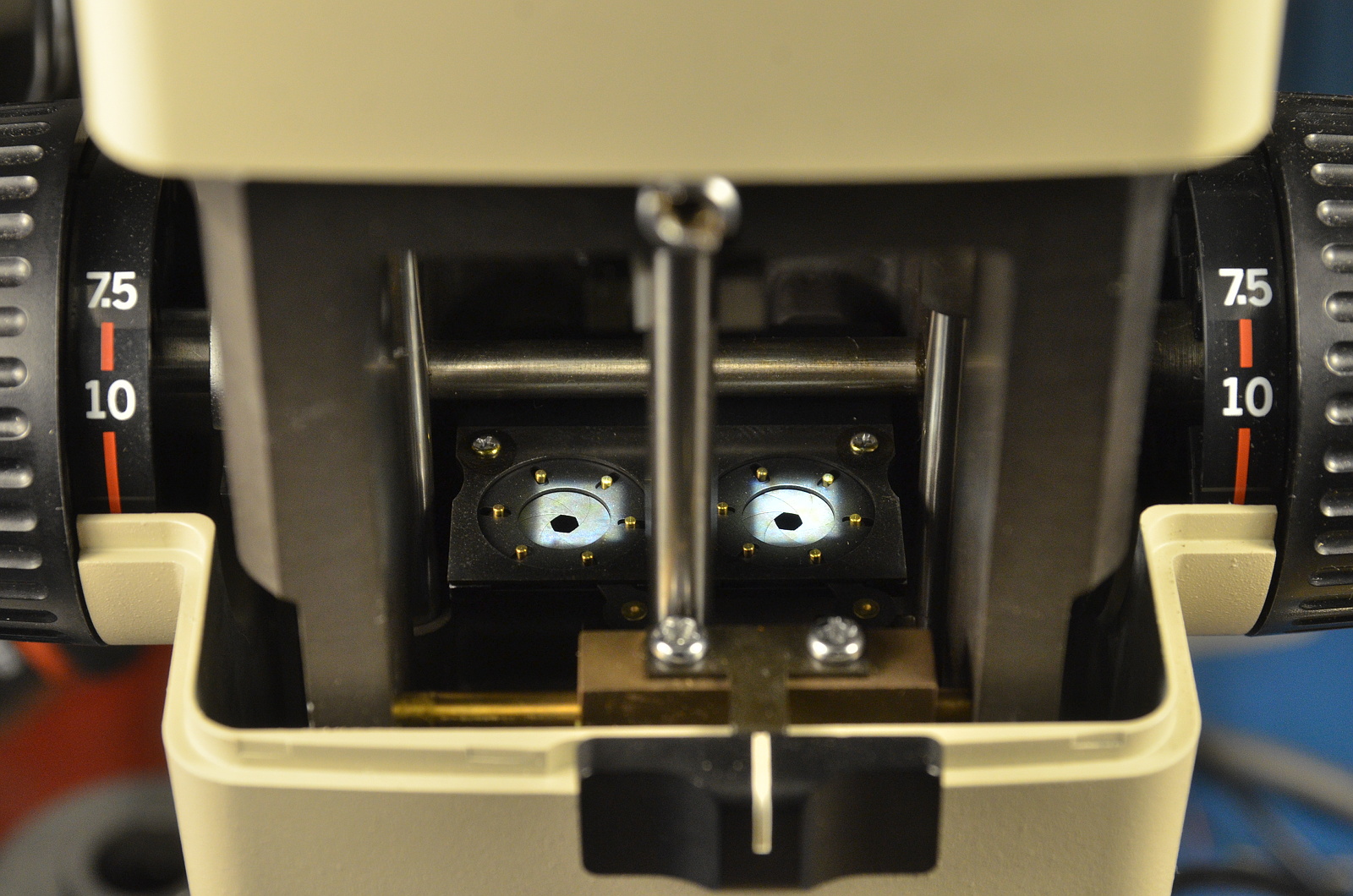
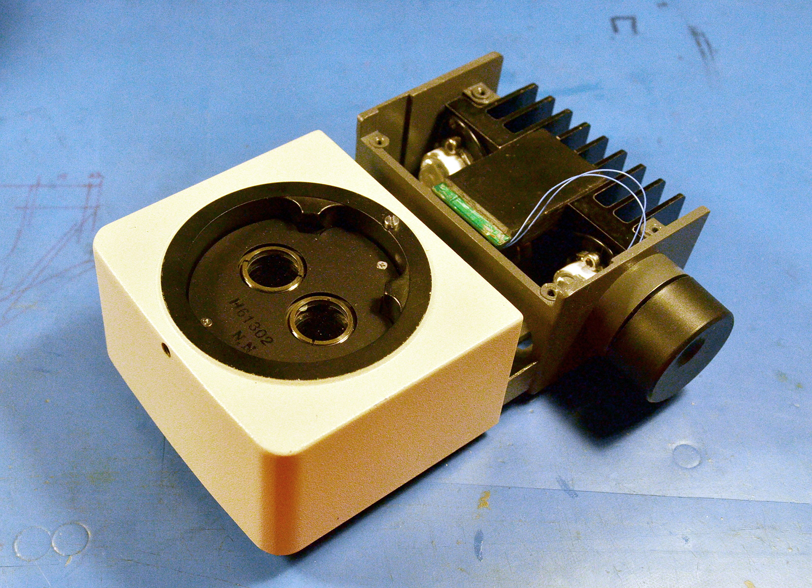
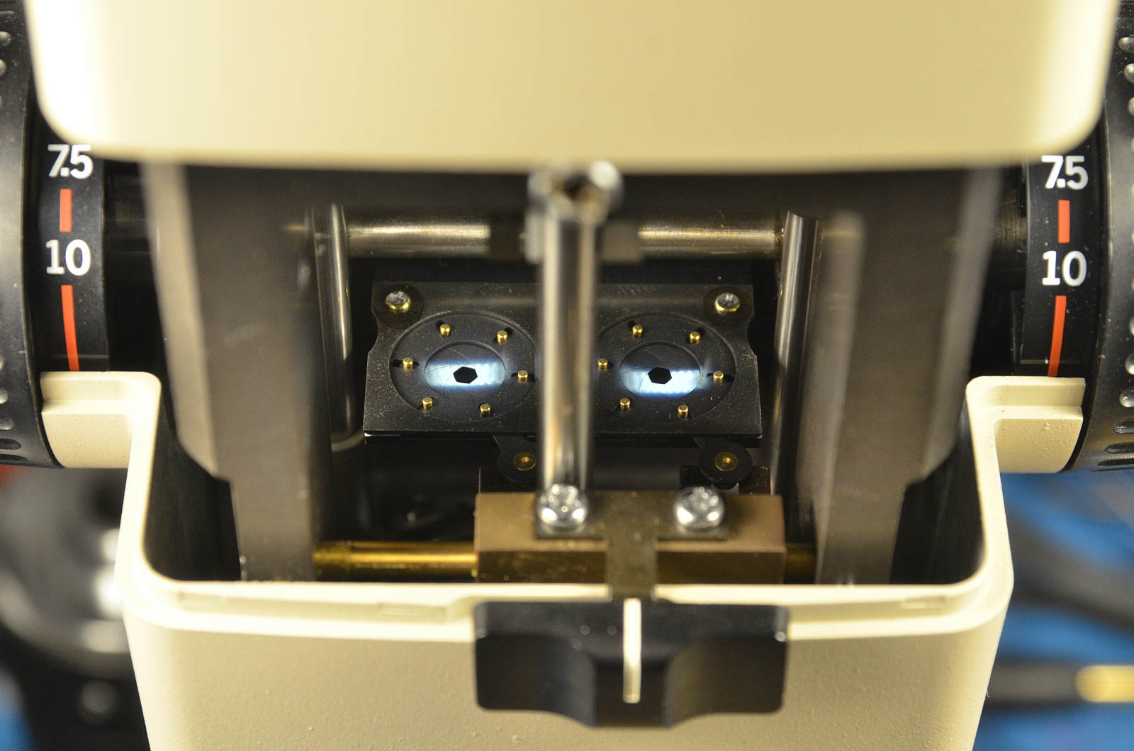
A little investigation reveals our problem is at the primary constraint in the optical path. Specifically, the coaxial illuminator is designed to focus down an image of the light source right at the plane of the internal adjustable iris in order to get as much useful light through it as possible. You can see the glowing filament clearly when the iris is nearly closed, and it passes through cleanly with the iris open.

When the light doesn't clear the iris but shines on it instead, the light pollutes the image. Interestingly, this means the adjustable iris and coaxial illuminator don't really coexist well, a problem I hadn't noticed before but yup.... sure enough... the illuminator is only really useful with the iris wide open.

Possibly for this reason, the slightly later SZH10 dispenses with the adjustable iris for a fixed aperture, instead offering the iris as an accessory 'slice' that can be placed later in the optical path. This neatly avoids the contrast problem.

In any case, my problem is 90% a slight misalignment, easily dealt with.

That said, the square die image is just a bit too large to fit cleanly through the round iris opening even when aligned. A little optimization of my illuminator optics is probably called for.

But... can I actually do better? Olympus knew what they were doing, and if there was an obviously better lens design they'd have used it, right?

Stay tuned for our next exciting episode!

xiphmont: (Default)

The end result of more playing around with the plastic LED collimaters: they're not going to work well. Dang.

The microscope wants a small diameter parallel light beam, and the plastic collimaters just won't do that. Even the tight spots overfocus and overmagnify, and there's no real room for adjustment.

Noq2's approach works because of:

a) brute force: 60W of LED light is the equivalent of around 350W of halogen light

b) a large die LED (7mm diameter!): that's more like a small COB

In his case it's a 'close enough' approximation to infinity focus because of the huge die and tons of output. There's enough nearly parallel light in there along with all the rest to make it work. Most of the light that makes it into the optical path (which is likely only 5-10%, the beamsplitter doesn't combine much) is just lighting up the inside of the microscope body, but the light that does make it all the way through is diffuse and even and nice. Brute force works!

Me, I want as much of the light to be usable as I can get.

So I'm probably back to using lenses. The stock Olympus setup uses two air-gapped elements with a total focal distance of 11-12mm placed on either side of a halogen bulb. The bulb filament intentionally sits just in front of the focal point to defocus the image slightly. (EDIT: Actually, I'm wrong here; it's just past the focal point in order to produce a focused image of the bulb filament at the point of the iris in the microscope body).

Olympus uses some really nice glass. The first condenser element is a partial shortpass to filter out some of the infrared. The second weaker element nearly touches the first and finishes the collimation job. Two 45 degree front-surface (!) mirrors direct the light into the beam combiner body.
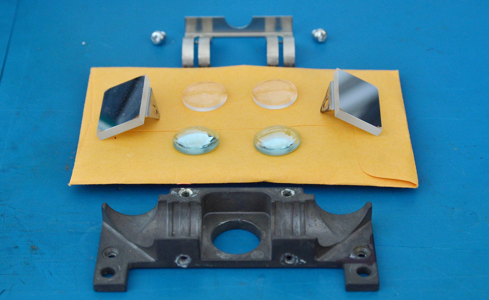
The biggest constraint on the collimater design is the diameter of the optical path through the scope, which is a little under 15mm at multiple points. Opposing that, we want to collect as much light as possible from the LED into the condenser, which means putting the lenses as close to the emitter as possible, and so choosing the shortest practical focal length. Focal length trades off against beam width; the shorter the focal length, the more the 'image' of the LED die is magnified and the wider the final collimated light beam.

The original Olympus optical design expands the image of the halogen bulb filament into a beam of approximately 15mm diameter, matching the optical path. The Cree XP-L LEDs I'm using have a die almost the same major dimension as the bulb filament.
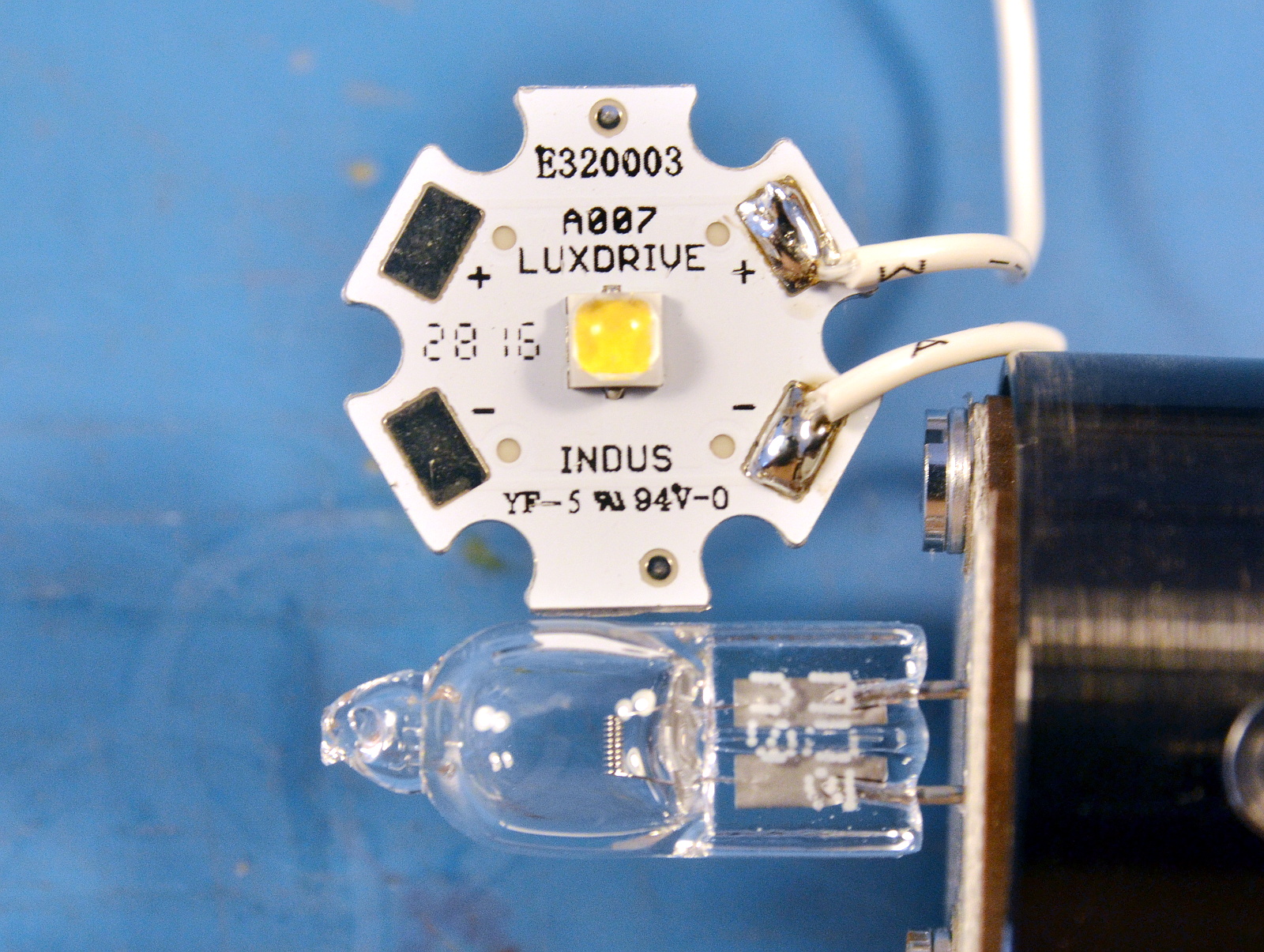
A more powerful LED with a bigger die probably isn't useful if we're going to use a single-stage collimator. And an XP-L is easily the highest-flux LED I can get with a die this small.

The XHP70.2 might put out 5x as much light, but if that's over 5x as much area, it's not a net gain given the constraints (I'm going to test it anyway, but I don't have high hopes). The big die of the XHP70.2 isn't a problem for noq2 because he's not using any optics that magnify its apparent size. He could usefully apply a 15mm COB.

This also means we're not going to improve on the original Olympus lens choices without going to a more complex beam reduction design that probably won't fit. (EDIT: Actually, I can probably fit a Keplerian design in there)

I'm going to try it Olympus's way. Given how dang nice those lenses are, I'm totally yoinking them. And since I'm messing so much with the physical layout, I want some adjustment ability. Which means at this point-- I'm most of the way back to my original design. Oh well. At least much of it is actually built and this has become an iterative process. A little at a time rather than one fell swooooooop.

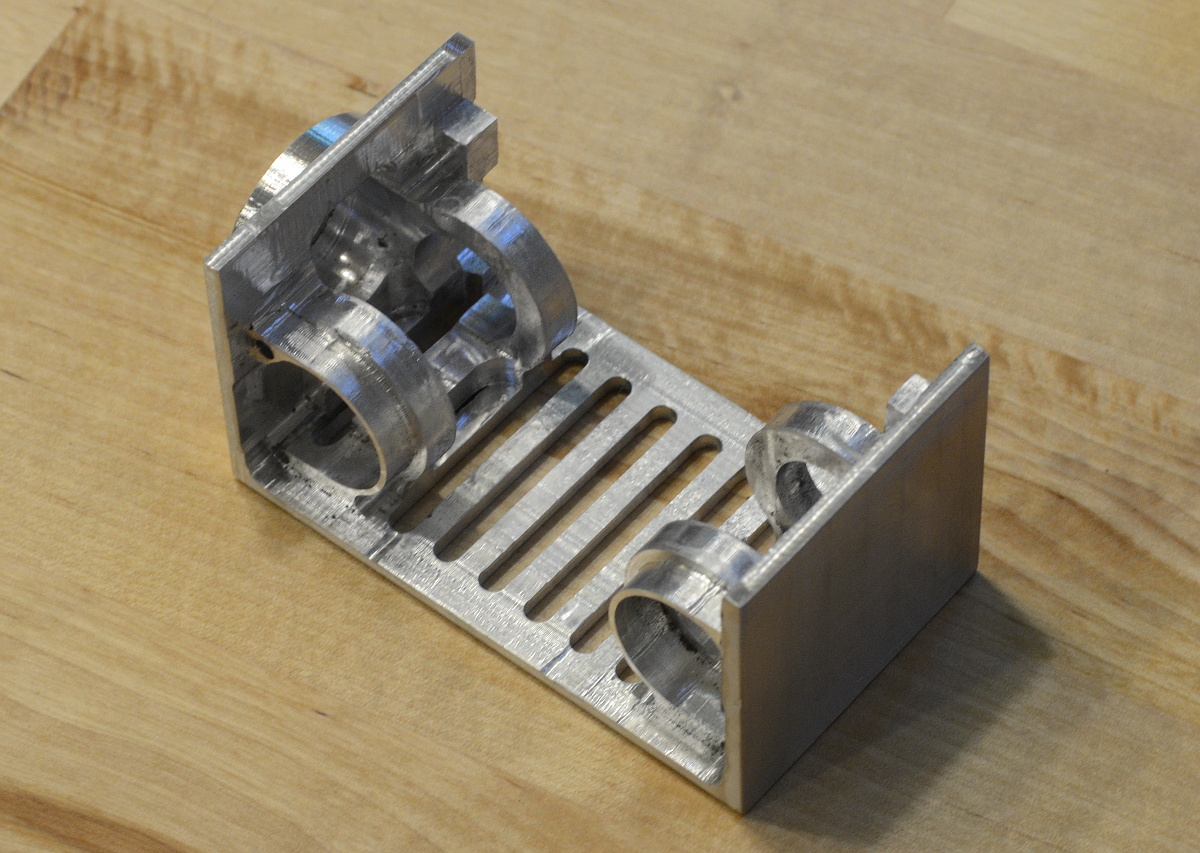
So... The next step is making some new lens tubes.
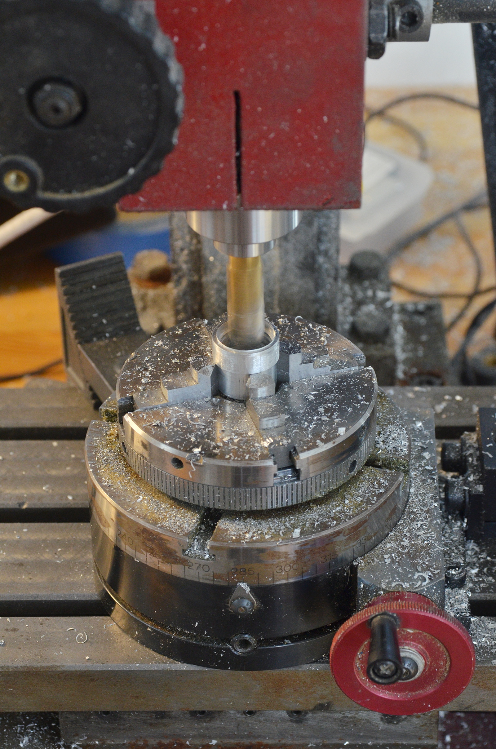
And mounting the Olympus lenses in them (using nice, reversible, not messy O-rings).

This gives me the lenses at the proper separation in a durable, flexible package. Now I have to make a tube mount that fits inside the lighting enclosure.
xiphmont: (Default)

Electronics assembly!

But does it, for the lack of a better word, chooch?

Yes, it chooches.

Adding the pot to test the adjustment, it turns out my BuckBlock is sourcing more than 500uA-- it's actually closer to 625uA. Also, it's firing up at ~1.5v rather than ~ 1.75v. That means I want a 2.2k low-end resistor and a lower pot resistance. So I modded another 10k linear pot into a 13k exp-ish pot, and continued assembly.

Everything goes together as intended and looks nice.

But there's a snag; I knew there was a good chance the optics wouldn't play as well with the SZH as I hoped, and in fact, the focus behavior isn't working well once on the scope. The illuminator works, and alignment is spot-on, but it's focusing an image of the lens at working depth, which is suboptimal. Also due to the suboptimal focus, lots of light is getting wasted inside the scope as it scatters out of the parallel-light/infinity focus portion of the optical path.

I'm going to have to play more with it.

xiphmont: (Default)

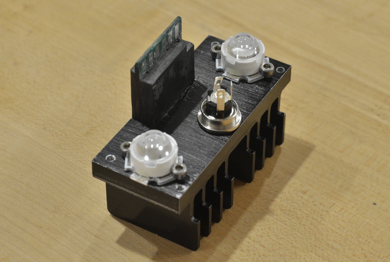
After evaluating several different canned collimators, I chose the oddball Ledil Tina spots as having the best behavior when used with the illuminator head optics. They're stick-ons, so I stuck 'em on, and added a few tacks of UV-cure resin as well.

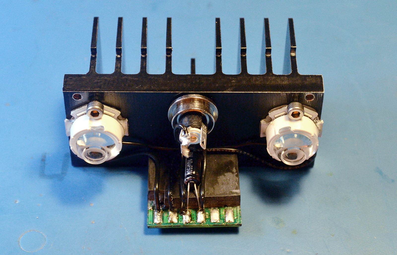
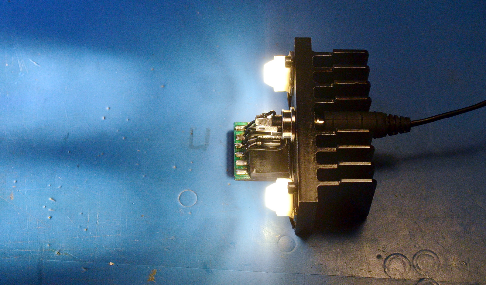
Inital heatsink assembly with LEDs, DC jack and BuckBlock looks good!

The intensity adjustment on the BuckBlock is voltage controlled and sources 500uA; the data sheet suggests feeding it through a 20k potentiometer to ground. That has two [minor] problems.

I'm using a pot with detents, and the way the adjustment curve goes, I'd end up with dead notches at both ends of the adjustment range. Second, the adjustment curve is linear and it would be nice to have more resolution in the low range. Intensity perception is exponential.

The first problem could be solved by using a 15k pot and adding a fixed 3k resistor at the lower end. The second problem is usually solved by using a log-taper pot (or in this case, I'd need an exponential, so I'd hook it up 'backward'). The problem is no one makes log-taper 15k pots, and certainly none with detents. Also, I already have linear-taper 11-detent 10k pots, and I don't feel like wasting them.

The usual trick of turning a linear-taper pot into a log taper with an extra resistor doesn't work here. I need an exponential taper, not a log taper. This is where older tinkerers usually start whipping out transistor circuits, and the more recent crowd embeds an entire microcontroller and writes software to get the desired curve.

I'll admit I played with a transistor circuit for a little while but my pots turn out to have a third problem-- the first and last steps are 1/5th the step size of the middle eight. That's when I realized I didn't want to work around a suboptimal part. The right part makes all these complications go away, and I can have the right part.

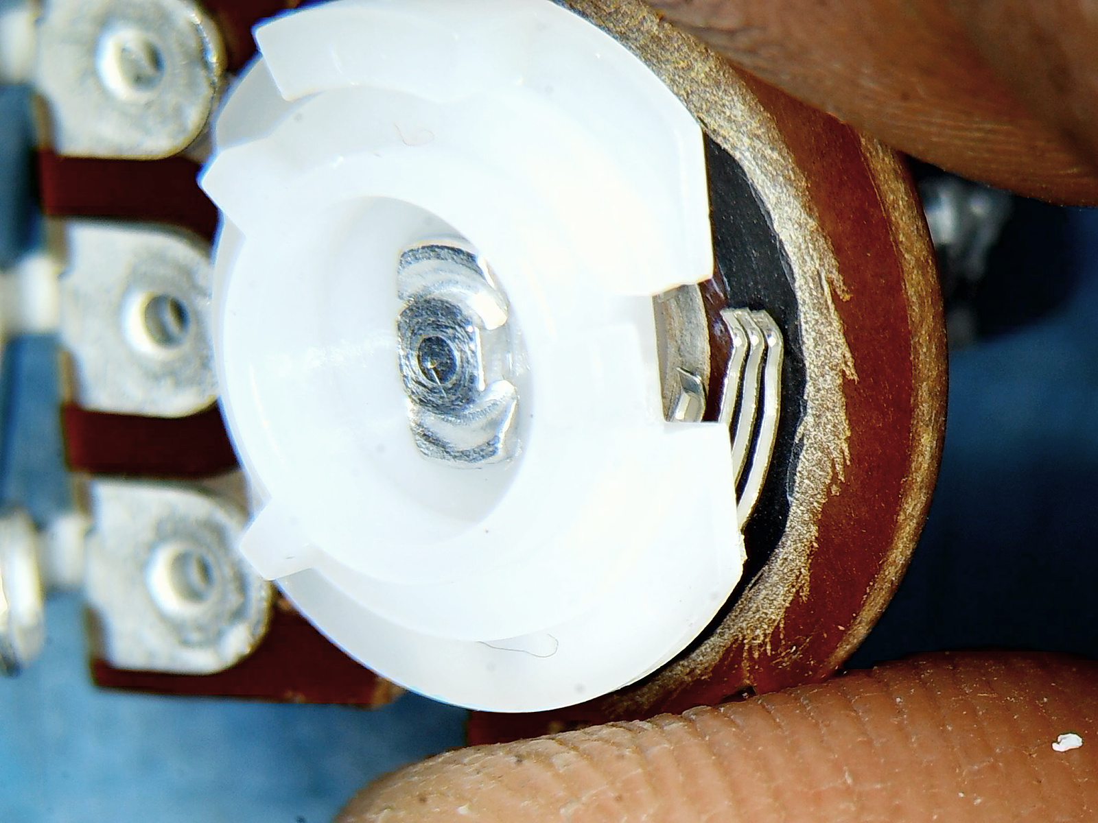
These pots are just carbon-element-on-phenolic-inna-can. So I pried the can open, and scraped the resistance element into the resistance and curve I wanted with a hobby knife. I cut the last step into an open (which will cause the adjustment's current source to float up to full-range), and trimmed the first step down to give a bigger step.

Now I have a the right part: a 15k pot that goes exactly to full-range in increasing steps. No additional electronics.

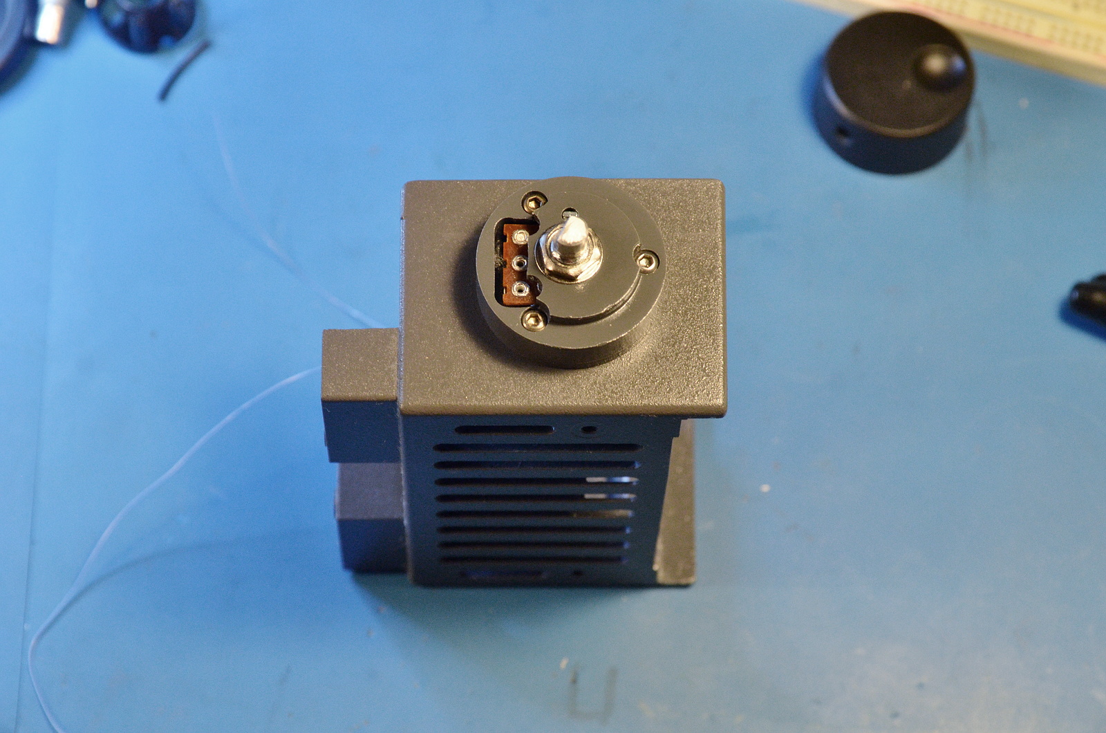
Today's work is done: I need to let the silicone holding the BuckBlock in place cure and the paint on the adjustment boss dry. Tomorrow I wire it up and test the assembled electronics.

xiphmont: (Default)

Earlier this year, when I was building mods for my Olympus SZH microscope, I planned a coaxial illuminator using LEDs. The design got... a little out of hand...

...and I put it aside.

Last week I stumbled upon noq2's blog, where he documented his LED mod for the same microscope. It's the polar opposite to what I was doing. His is simple, brute force, and gets the job done. Go have a read, it's nicely done (and his animated gifs of the SZH internals are great). And did I mention it's actually finished and working? :-)

This inspired me to reconsider what I was doing.

I mean, I know what I was thinking: a design worthy of the rest of the absurdly overbuilt Olympus. I mean, just look at the original collimator! They use front-surface mirrors in the light source!

Also I didn't want to sacrifice any original Olympus parts. Complete SZH coaxial illuminators still sell for over a grand. But that's mostly because they're usually missing accessories needed to operate them (the bulb holder and transformer) which I didn't need. Last summer I picked up a bare illuminator block for $90. That's cheap enough I'm willing to mod it permenently.

Then I saw noq2's build. It was brilliant. And even better, I can have everything I originally wanted with a dead-simple addition.

The whole 'tactical flashlight' craze has spawned a smorgasboard of cheap, canned collimation optics for LEDs. They're even better than lenses as they sit all around the emitter instead of a distance in front, so they catch more light. Most are 90%+ efficient.

So I'm taking what noq2 did and slapping a $2 spot-collimator on front. No muss, no fuss. Well, I have to fuss a bit, so I'll put the driver electronics inside the housing, and add an intensity adjustment too. Still not *much* fuss.

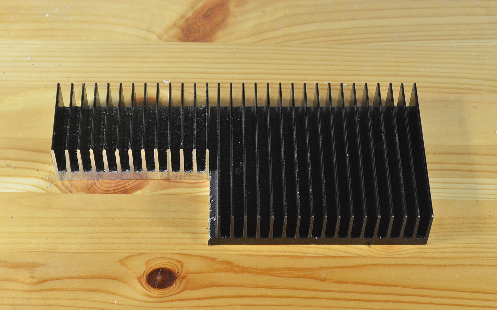
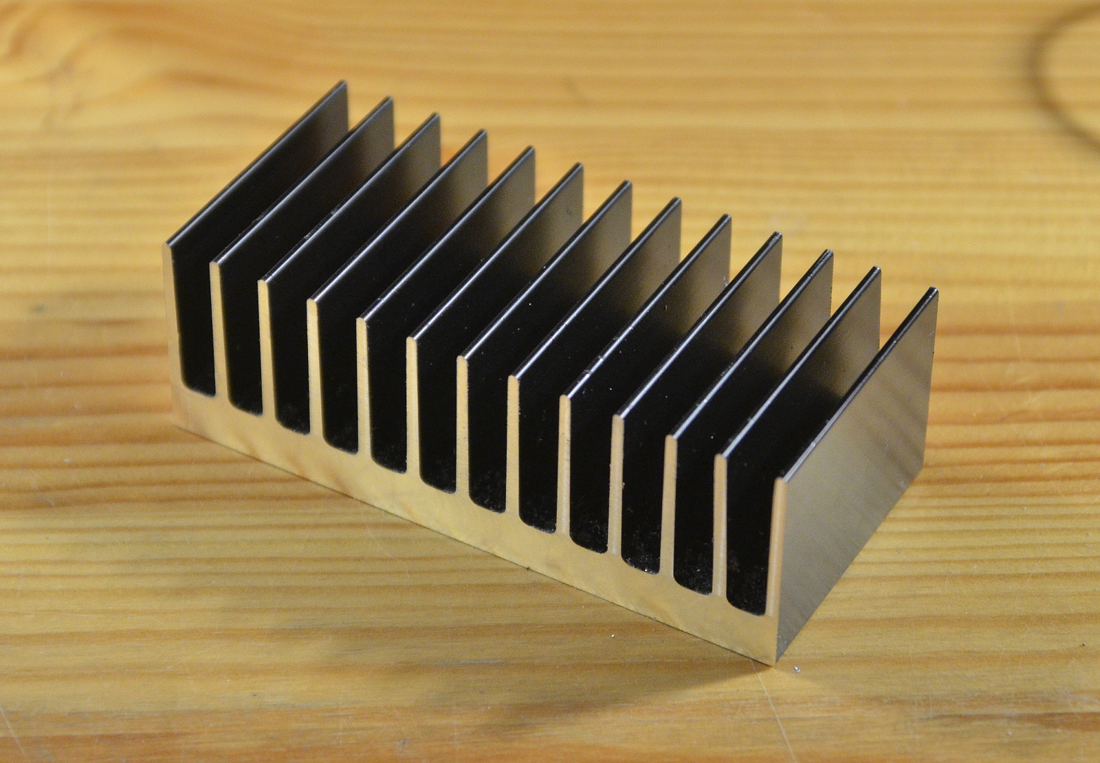
...beginning with hacking off a big ol' chunk of heatsink using a dull beaver...

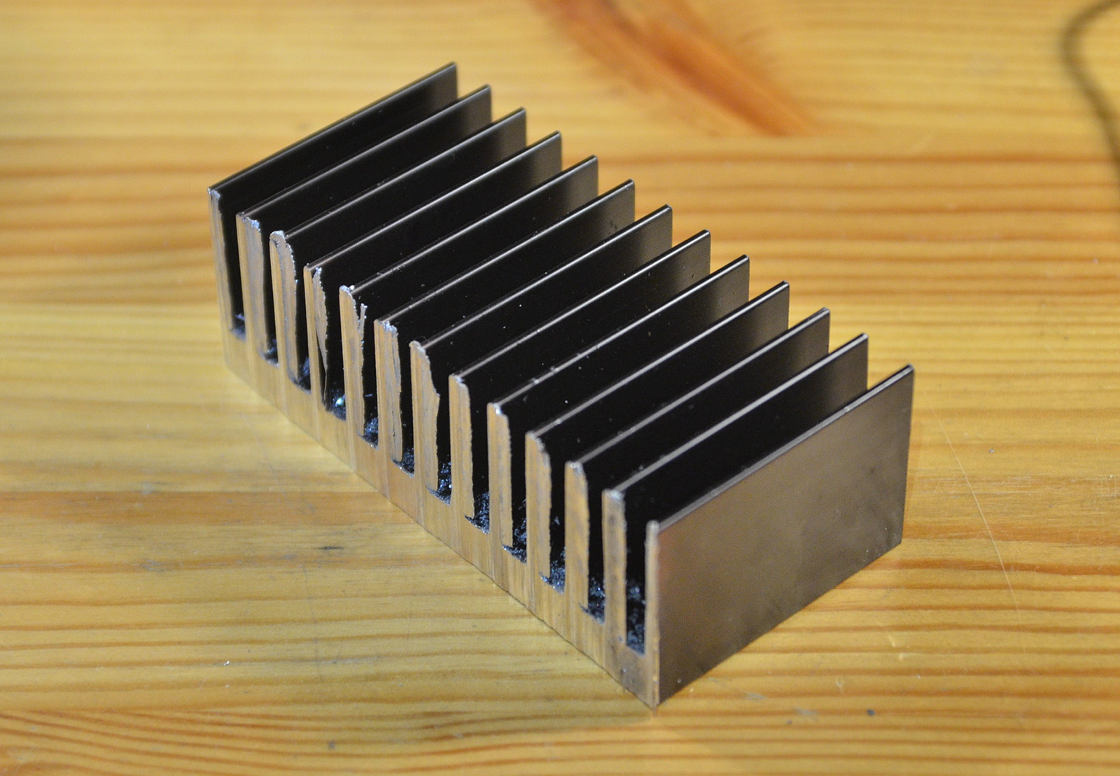
and cleaning it up a bit on a sharper beaver.

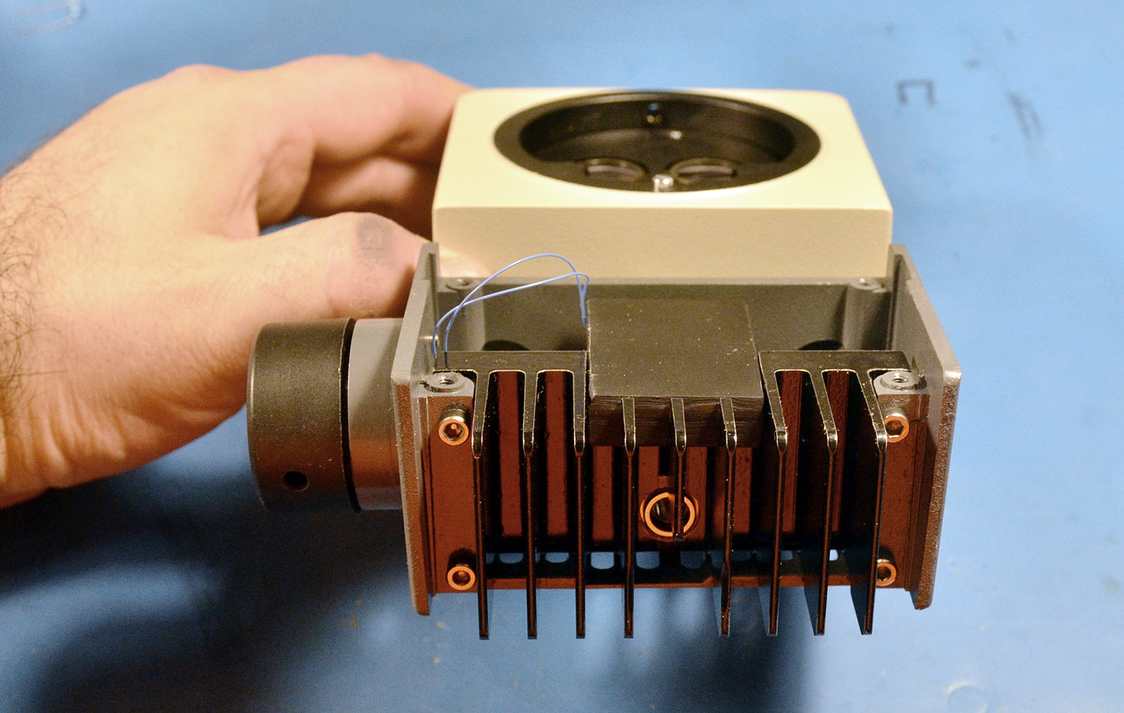
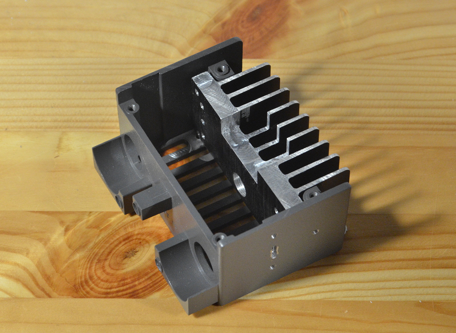
Trim to fit the existing enclosure, with an eye toward reusing the existing mounting holes on the enclosure's rear boss. Also drill and tap holes for LED mounting, power jack, and a notch for a BuckBlock controller, and we end up with something like:

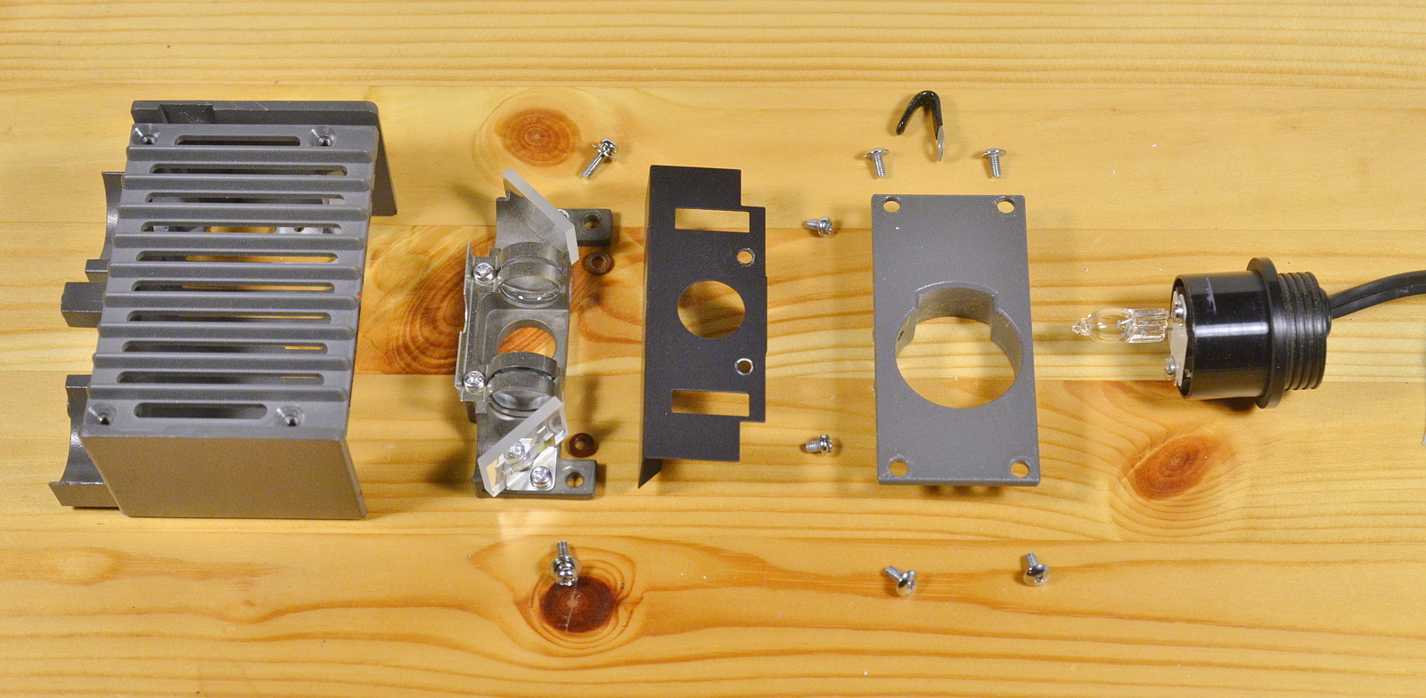
I want an intensity adjustment knob, so I stole the boss off the prototype I machined earlier this year. Along with bolts, a really nice 11-position-with-detents potentiometer, and the aforementioned LED optics (but not including wires) we finally end up with this exploded build:
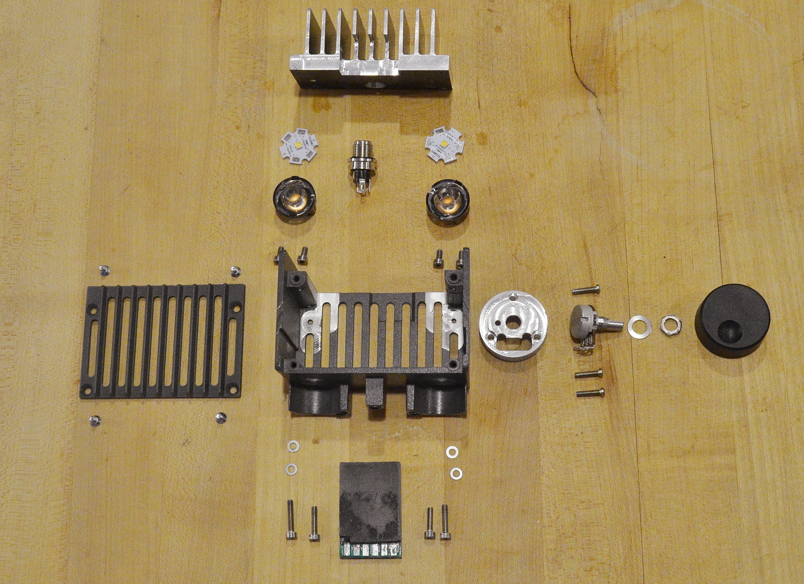
Next up will be a little paint, a schematic, and build/test.

xiphmont: (Default)

There's some good LCD news though-- I found a seller who's trickling out small numbers of refurbished HV121P01-100 screens, and unlike all the others I've sampled in the past several years, these have so far been excellent. Yes, they're rebuilt, but they appear to use entirely genuine, model-appropriate parts. I have no idea if these are parts from B-grade panels being reassembled into new screens or what, but the results are NOS visual quality.

There's a 'downside': he actually seals the panels together with black RTV silicone. If you want to open the panel up to do further surgery, you can't. Or rather, with a thin spudger, a ton of patience and very very steady hands you can, but slip once and you'll crack the matrix. I did open some up to have a detailed look--- Yup! All genuine inside!

If you *don't* have any reason to open the screen up, the black silicone is a good idea-- it keeps grit out, and prevents the dreaded 'white spots' from ever developing. I've considered building screens this way myself, so I actually approve.

I'm importing a few of these for conversion to LED. If you want one, contact me about it. If you want to order directly yourself, it's item #710816705 on AliExpress. I have no idea how many per month he can actually make, or if the quality is going to hold up, but so far, so good!

xiphmont: (Default)

I've previously regaled you with stories of poorly rebuilt SXGA+ screens being sold as new that are the bane of X62 builders. Whelp, I'm beginning to think just about every in-demand LCD panel on AliExpress stands a good chance of being a barely serviceable, cobbled together pile of poo. Usually sold as "NEW" or "GENUINE" or "100% ORIGINAL" of course.

I'm building some T70s now, and the screens folks like to have in these are the IAQX10 2k 4:3 AFFS screens from the old IDTech joint venture. Like the SXGA screens for the X62, these are long out of production, still in demand, and hard to find in the wild. I've been working out how to mod the much thicker industrial -M version, which uses the same matrix, to work in a T70.

While I'm working that out, an IAQX10N seller pops up on AliExpress. The screens are expensive, but a genuine laptop version of this screen should be expensive at this point. I decided to buy just one so I had a comparison for my rebuild efforts.

Screen arrived, and lo and behold, it's a cobbled together pile of poo.

Immediately upon opening the box: the screen has a gloss front polarizer film. Uh oh. Stock is matte. Looking closer, it isn't even cut straight. Like, guys, at least use a straightedge.

Well, let's see if it at least works... and find it has a blank EDID. Uh huh. OK, let's get an IAQX10N EDID into it...

and we get:

The background on that screen? It's not supposed to be blue. It's supposed to be black. No, I didn't mess with the photo. 'Black' really looks like that. It's measuring less than 100:1 contrast; that blue is backlight bleed-through.

And the diagonal stripes? Not a trick of the picture. They're really there. It's Moiré patterning from using the wrong prism films for the given DPI, or not tacking them in-place and having them shift in transport.

This may well be the worst refurb job I've seen to date without being bent or cracked. Actually, I take it back, the outer frame is also slightly bent.

But hey! I'm only out $100 in shipping once I return it!

(In case you were wondering, the protective plastic film is still on the front of the screen in that picture, so all the bubbles and scratches are not real defects. But it does mean they did a lousy job putting the film on.)

xiphmont: (Default)

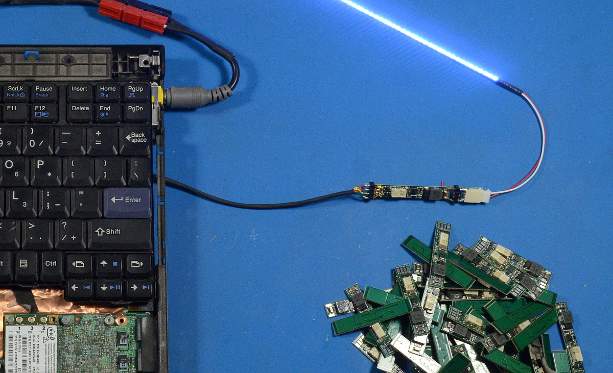
I've modded nearly 300 X61 inverters to drive LEDs over the past four years, and I thought I'd seen all the possible FRUs. NOPE.

Not listed in the hardware reference or parts cross-reference: the Sumida FRU 41W1024. Undeniably an X61 inverter.

And here it is, before modification, for reference purposes.

xiphmont: (Default)

The prototype boards are back from OSHPark. Dang, they did a really nice job.

Not perfect, but the cosmetic errors are mine; I submitted the protos to about 10 online PCB joints to see who'd actually make them to my DRC spec, and a few bits like silkscreen holdoff didn't actually match everywhere. I can adjust that for a real run.

OSHPark was one of two places willing to do 6mil/6mil 2oz without several rounds of human intervention. The other is DirtyPCBs, and I can't wait to see what comes back from there. Suffice to say I hope they're serviceable (as they're about 1/10th the cost in batches of 100), but it's highly unlikely they'll be as nice as this.

Maybe I can push the rest of the BOM to be able to afford the difference, I really like these...

xiphmont: (Default)

When I first offered LED conversion kits, I got the inverters I modded for free from forum members who sent their spares, supplemented by bulk lot buys of used boards from eBay. For the first 200 kits or so, I paid on average about $5 a board, which I then modded with the custom LED hardware.

The supply of X60 and X61 inverters is drying up, which is not to say they're no longer available, but they're now well into legacy pricing. Min price is about $20 apeice now.

Building complete inverters from scratch was probably always cost effective, but I just couldn't find the discontinued connectors I needed. I think I have those secured now, so I spent a few days of free time consing up a new inverter board design.

The prototype is off to OSHPark for fabbing! It's nearly the same schematic as the TLD3, but the layout is from-scratch to make it easier to assemble.

Pseudorama

Nov. 29th, 2017 07:48 pm
xiphmont: (Default)

I'm about to ship my 250th ThinkPad LED backlight kit, all hand-assembled and soldered. I had no idea. I expected there to be demand for about ten. The kits are for models over ten years old... and demand is still increasing.

Not pictured: The stack of 30 different headless ThinkPads I use for kit testing.

xiphmont: (Default)

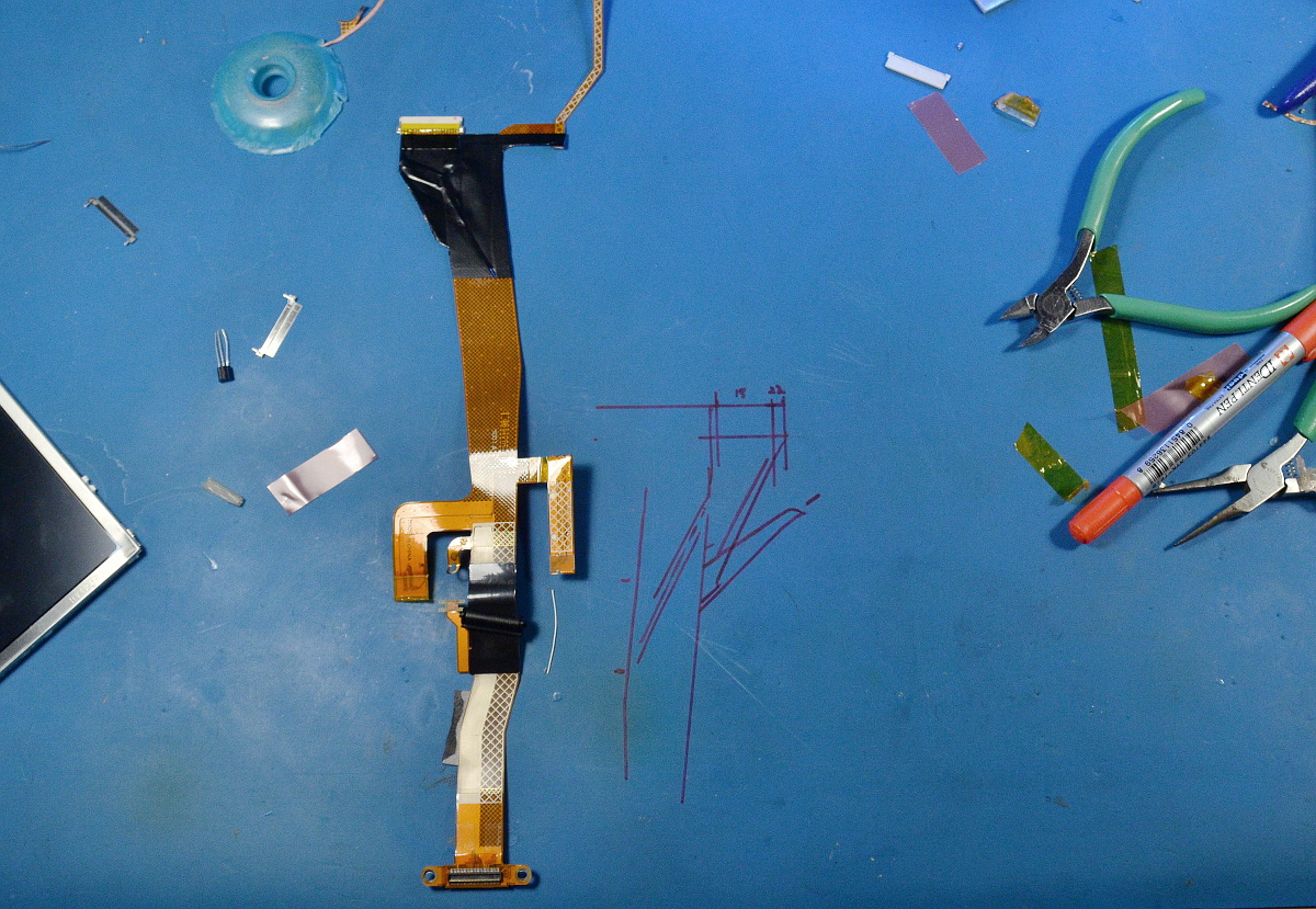
...so yeah, I'm apparently also in the custom Thinkpad LVDS cable business now. This one lets an X61/X62 motherboard use a 4:3 12.1" SXGA tablet screen. I'm still practicing, but I've found a source for 100 cables cheap...

xiphmont: (Default)

....w00t! Found the missing Thinkpad inverter stash! That should hold me through Christmas.

xiphmont: (Default)

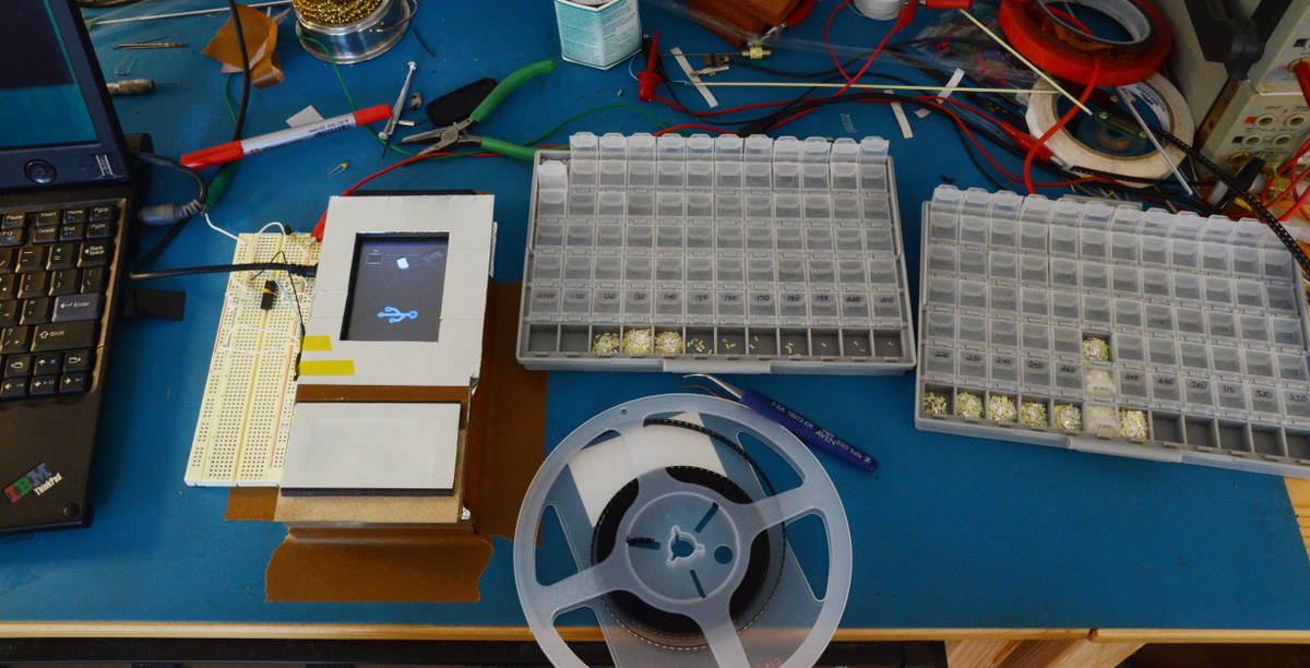
...only 1000 left to bin on this reel....

xiphmont: (Default)

Another catch-up post.

A few weeks ago, I accepted my first order for a T43 backlight kit. It turned out to be a c-c-c-c-c-combo-breaker!

In the early days of software-controlled brightness, ThinkPads used an analog brightness signal like just about every notebook. It was generated by one of the D-to-A pins on the embedded Renesas H8S microntroller all ThinkPads used.

As of the X40, ThinkPads went to using a digital PWM brightness control generated by the Intel Centrino ICH Southbridge. This made them kind of weird by laptop standards. It's one of the reasons I had to cons up custom LED drivers for my ThinkPad brightness kits.

In general, the T and X series of the same generation shared a basic architecture. The planars were quite different, but the chipset and basic design were the same. Not so with the T4X and X4X.

The X40-series is a completely different design from the T40-series. It uses a PWM brightness control. The T40, however, is analog like the older machines, which threw me for a loop at first. The good news is that I'd made working drivers for the X2x, X3x, T2x and T3x beforehand, so once I realized the T4x was an 'old' style, getting it to work wasn't hard. I can use the same positive-analog TLD2 hack that worked on the earlier models.

The bad news is all my fabrication, based on the TLD3, is geared toward the PWM-based ThinkPads. The TLD3 boards aren't able to use a positive-analog brightness signal no matter the hack. For a TLD3, it's PWM input or nothing.

I have on hand ~ 1500 TLD3 PCBs, waiting to be populated, for the usual PWM kits. I have only ~ 20 TLD2 PCBs left that can be pressed into analog use.

Get 'em while you can.

xiphmont: (Default)

Packaging of the Chinese backlight kits I used to order tended to be... disappointing. Parts arrived broken on a regular basis, and there was never any moisture or static protection.

As a result, I put a little effort into my packaging.

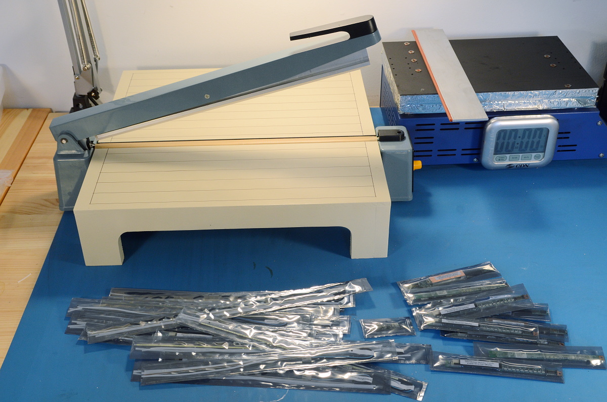
With a paper cutter and an impulse sealer, it's easy to make moisture and ESD-proof bags of any size. The little table around the sealer was a quick afternoon toss-together made of MDF and a quick layer of paint. It locks into the lip along the bottom.

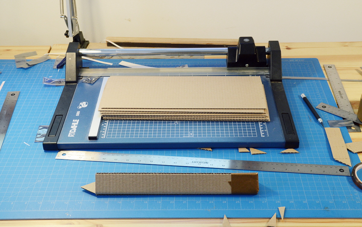
And of course, I make my own boxes! ThinkPad modders have taken to calling them Toblerones, which is kind of obvious, really.

xiphmont: (Default)

The ThinkPad LED backlight kits consist of two major pieces; an LED strip and an LED driver. The driver boards are designed to fit onto existing CCFL inverter boards after removing the CCFL step-up coil.

For good measure, I pull off the CCFL driver chip as well. Simply disabling it doesn't keep it from drawing a [very small] amount of current.

Removing the driver chip also opens up additional possibilities for reusing traces on the existing PCB. I don't like running long wires across the width of the inverter when hooking up the LED driver board. They'd need to be glued down to avoid accidental snagging, and that's a complication I don't need.

Instead, I re-route power, ground and the ENA and DIM signals through the original board, using solder bridges and 0-ohm bridge resistors where possible. On most boards, one or two jumpers are still needed, though a few boards I can get away without using any.

This work is most definitely all done under the microscope.

That also reminds me-- I need to get my library of reference modification pictures up somewhere.

xiphmont: (Default)

The first step is admitting you have a problem...

The problem being, specifically, that this stuff does not come in gallon cans.

xiphmont: (Default)

The LED strips are the big reason I still pick-and-place everything by hand. My tolerances here are just a few mils, and I've machined myself steel-and-aluminum templates to make the placement easier.

The idea is actually to place with looser tolerances, dropping the LEDs into the trough where the strip is clamped the check spacing and orientation with the microscope before reflow.

During reflow I tighten the guides on the jig and level the LEDs using a little precision squeegee I made out of aluminum and high-temp silicone.

Once the strip cools, I can pull it out of the jig, remove excess solder beads under the microscope, check for obvious defects, test on a power supply, and wash down with flux remover. Then it's on to applying the teflon layer, soldering pigtails, an up-to-temperature burn-in and flex test, and finally packaging.

xiphmont: (Default)

Initial functional testing of the LED drivers is just to find obvious reflow defects, mostly solder-bridges and non-obvious tombstoning.

Read more... )

Profile

xiphmont: (Default)
xiphmont

Syndicate

RSS Atom

Most Popular Tags