Time To Make The Donuts
Jun. 9th, 2017 12:13 pmInitial functional testing of the LED drivers is just to find obvious reflow defects, mostly solder-bridges and non-obvious tombstoning.
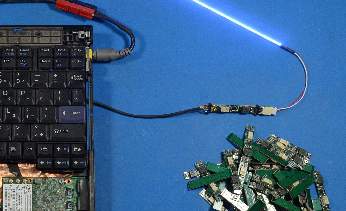
I have a simple test harness that plugs into an X61 on one side, and has a small connector (made out of a male header) on the other side that slips over the four input pads on the driver. I have a similar adapter made from another header and a CCFL connector harvested from a broken inverter board to plug into an LED strip. It only takes a few seconds to test that the driver lights, and that the enable and brightness inputs work properly.
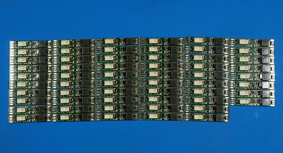
Of the 58 drivers I built in this batch (meant to be 75, but I mis-inventoried my inductor supply and only had 58), 54 worked properly. Of the remaining four, three were due to soldering defects on the driver chips, such as the solder bridge below.
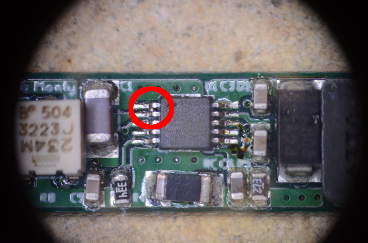
MSOP-10 is possibly my least favorite package, the paste requirements are very hard to get perfect by hand. Too little, and the lead has a weak or non-existant joint. Even slightly too much, and you get a solder bridge.
In any case, each of the four bad drivers were easy to rework into normal working condition, resulting in 58 perfect drivers ready for installation.