Donut Baking Pans
Jun. 17th, 2017 10:39 amIt tries so hard to look like an Olympus SZ series, but no.... not quite.
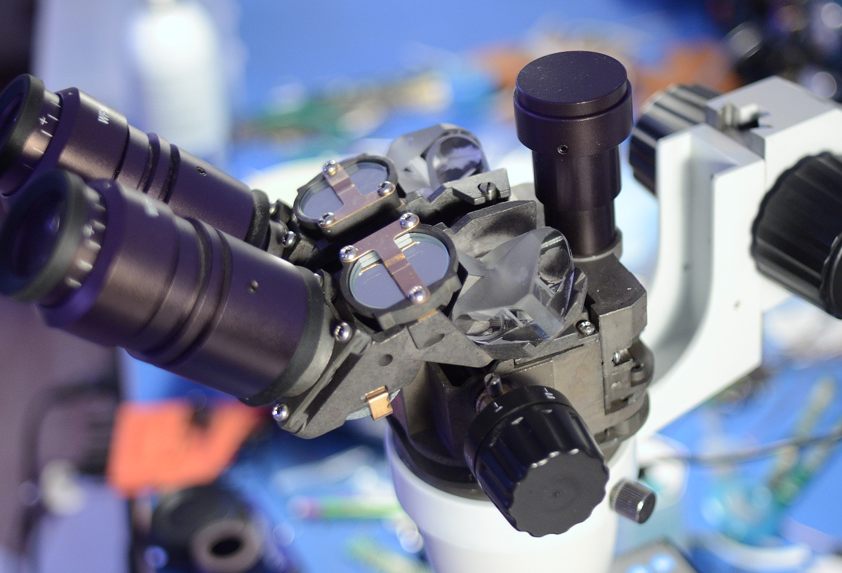
It's not actually terrible, it's fairly decent. But it's not the real thing either.
It tries so hard to look like an Olympus SZ series, but no.... not quite.
It's not actually terrible, it's fairly decent. But it's not the real thing either.
Packaging of the Chinese backlight kits I used to order tended to be... disappointing. Parts arrived broken on a regular basis, and there was never any moisture or static protection.
As a result, I put a little effort into my packaging.
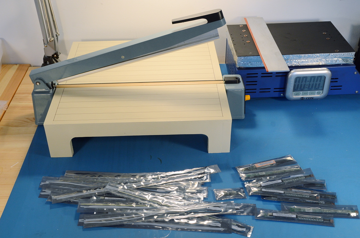
With a paper cutter and an impulse sealer, it's easy to make moisture and ESD-proof bags of any size. The little table around the sealer was a quick afternoon toss-together made of MDF and a quick layer of paint. It locks into the lip along the bottom.
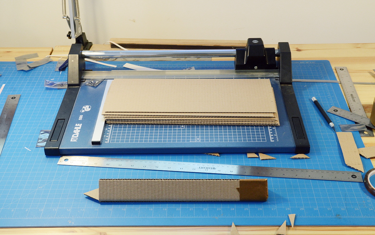
And of course, I make my own boxes! ThinkPad modders have taken to calling them Toblerones, which is kind of obvious, really.
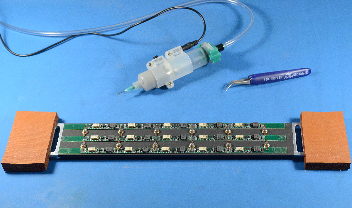
The ThinkPad LED backlight kits consist of two major pieces; an LED strip and an LED driver. The driver boards are designed to fit onto existing CCFL inverter boards after removing the CCFL step-up coil.
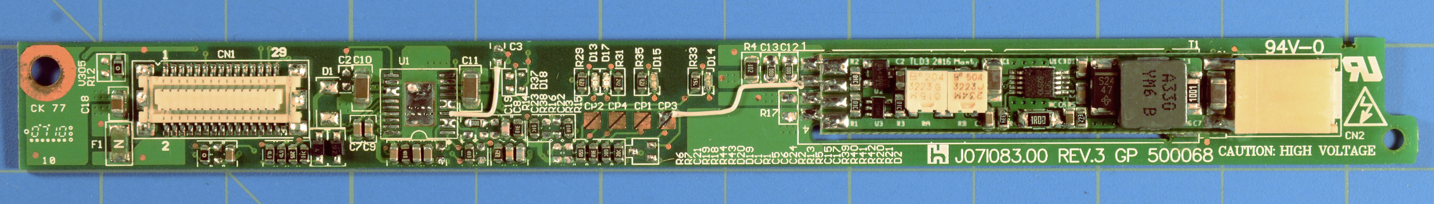
For good measure, I pull off the CCFL driver chip as well. Simply disabling it doesn't keep it from drawing a [very small] amount of current.
Removing the driver chip also opens up additional possibilities for reusing traces on the existing PCB. I don't like running long wires across the width of the inverter when hooking up the LED driver board. They'd need to be glued down to avoid accidental snagging, and that's a complication I don't need.

Instead, I re-route power, ground and the ENA and DIM signals through the original board, using solder bridges and 0-ohm bridge resistors where possible. On most boards, one or two jumpers are still needed, though a few boards I can get away without using any.

This work is most definitely all done under the microscope.
That also reminds me-- I need to get my library of reference modification pictures up somewhere.
The LED strips are the big reason I still pick-and-place everything by hand. My tolerances here are just a few mils, and I've machined myself steel-and-aluminum templates to make the placement easier.

The idea is actually to place with looser tolerances, dropping the LEDs into the trough where the strip is clamped the check spacing and orientation with the microscope before reflow.

During reflow I tighten the guides on the jig and level the LEDs using a little precision squeegee I made out of aluminum and high-temp silicone.
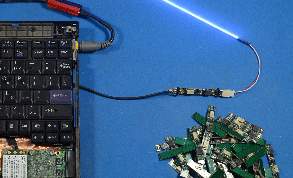
Once the strip cools, I can pull it out of the jig, remove excess solder beads under the microscope, check for obvious defects, test on a power supply, and wash down with flux remover. Then it's on to applying the teflon layer, soldering pigtails, an up-to-temperature burn-in and flex test, and finally packaging.
Initial functional testing of the LED drivers is just to find obvious reflow defects, mostly solder-bridges and non-obvious tombstoning.
 ( Read more... )
I'm currently on rev 3 of my ThinkPad-specific LED retrofit driver boards. They fit into the space on a stock inverter freed up by removing the CCFL step-up coil.
I'm on pace to make about 200-300 kits this year, and I'm still making them all by hand. Solder paste applied using a pneumatic dropper, components placed using tweezers and stereo microscope, then reflowed using a hotplate (thus the little placement jigs with silicone handles).
LEDs and LED strip PCBs are finally here!

So now it's time to catch up with the LED backlight kit orders, aka, I know where all my free time is going the next few weeks...
(Does anyone else still remember the Dunkin' "Time to make the donuts" commercials?)